| ID |
Date |
Author |
Category |
Type |
Subject |
|
33
|
Tuesday, May 02, 2017, 16:52 |
Isaac Earle | BL4N | Development | BL4N 35-deg bender stand hardened parts tested |
Hardness testing was performed on 1 sample each of parts TBP1822 and TBP1823 (part of the 35-deg magnet stand assembly TBP1804), They were found to be 60-60.5 Rc and 60-61 Rc respectively which is within spec. The alloy used to fabricate these parts was AISI #8620. The testing was performed by Precision Heat Treat in Surrey who also performed the heat treatment at an earlier date. |
|
35
|
Thursday, June 01, 2017, 15:25 |
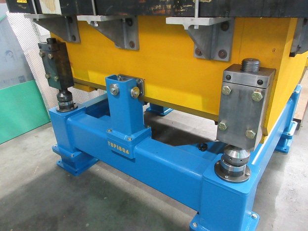
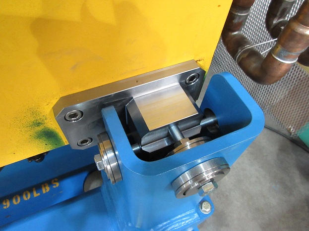
Isaac Earle | BL4N | Development | BL4N 35-deg bender adjustment blocks modified to fit magnet |
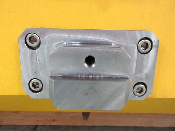
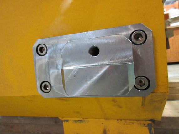
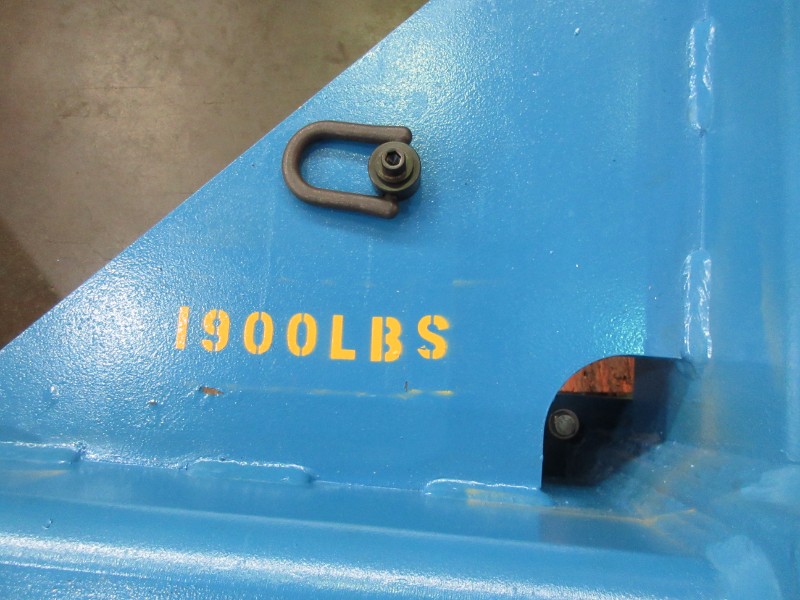
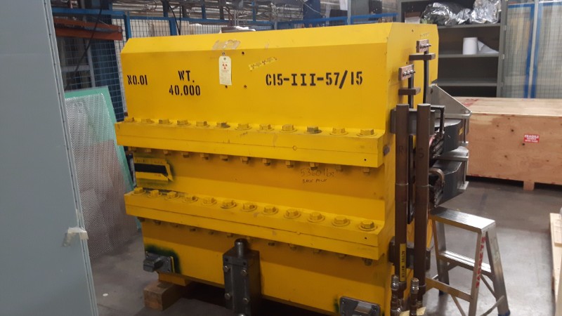
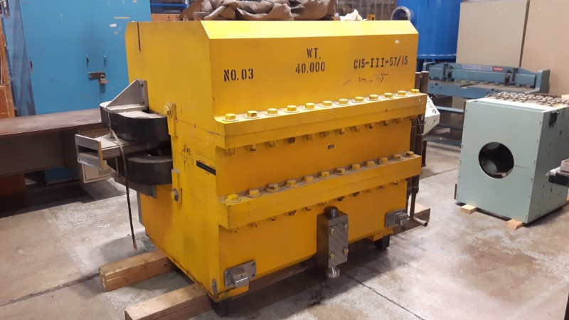
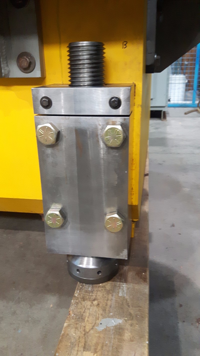
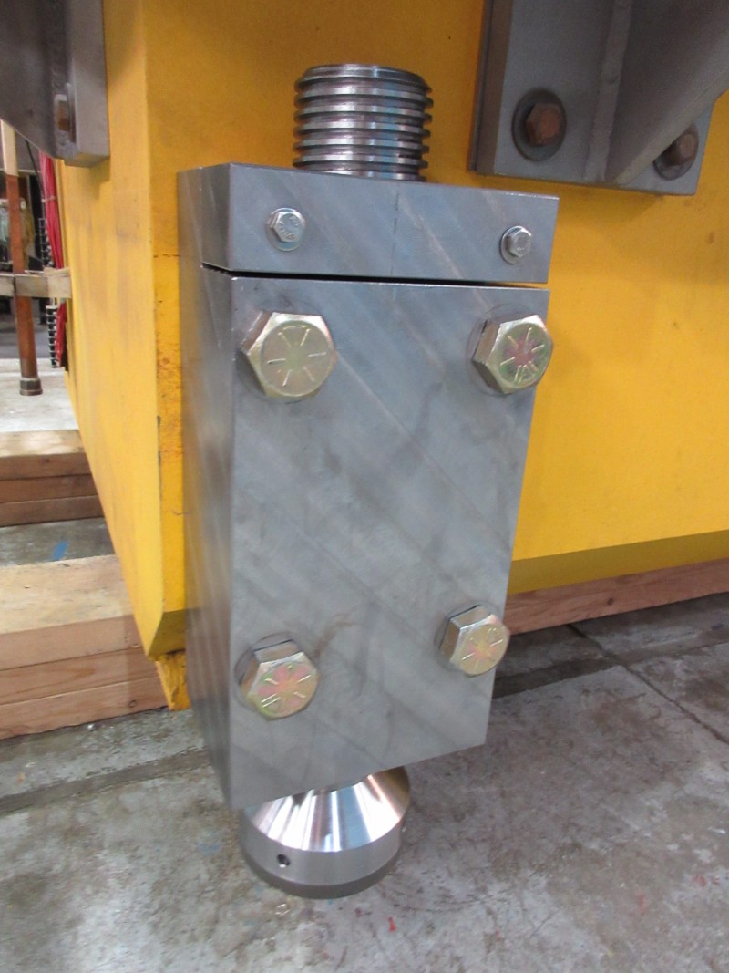
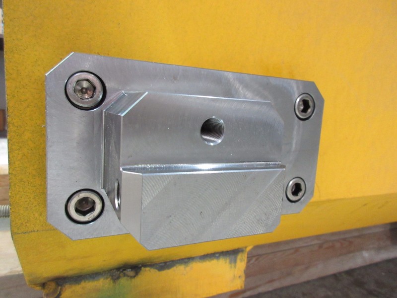
Adjustment blocks were installed on the second dipole bender today (labeled "No. 03" "C15-III-57/15"). The mounting holes on the magnet were not aligned properly, so modification was required for two of the blocks. The counterbored holes on TBP1809 were slotted 0.10" vertically, and on TBP1808, 0.06" horizontal slotting was required. A stress analysis was performed to confirm that the blocks are still strong enough to withstand the seismic loads (PDF attached).
|
| Attachment 1: Stress_analysis_on_TBP1808_and_1809_for_modification_to_fit_magnet_-_June_1_2017.pdf
|

|
|
36
|
Monday, June 05, 2017, 16:16 |
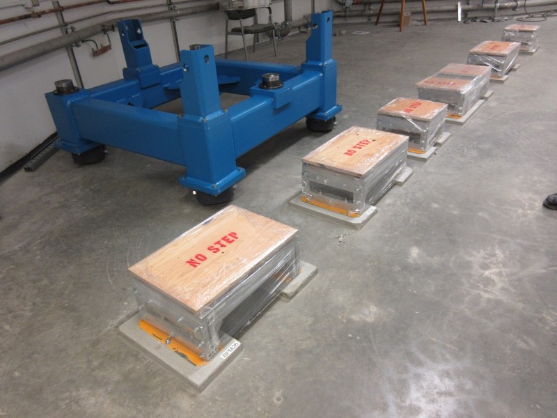
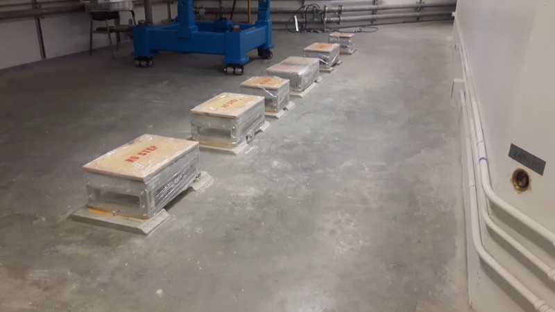
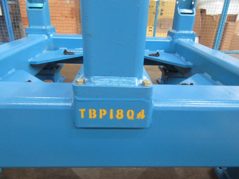
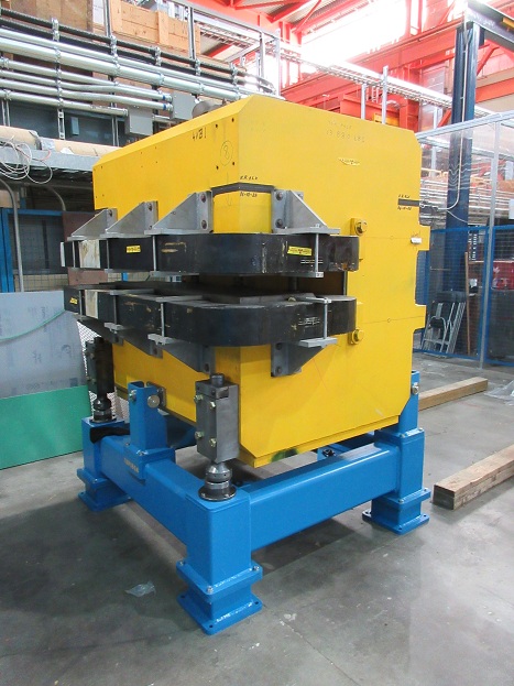
Isaac Earle | BL4N | Development | BL4N 35-deg bender stand assembly complete |
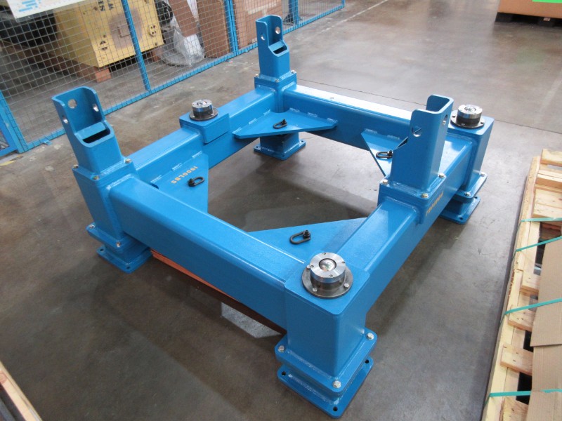
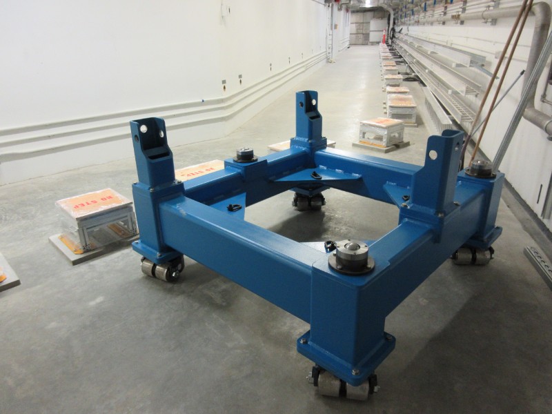
Assembly of two complete bender stands was completed on Friday June 2nd as well as installation of new hardware on the dipole magnets for support, adjustment, and seismic restraint. All parts were installed according to drawing TBP1804.
One of the frames was assembled with the caster wheel configuration. This frame was pushed from the proton hall B2 level to its final installation location in the ARIEL tunnel. The frame was a tight fit around the first corner around BPM 26 but it could still pass by without having to remove any items including the electrical boxes on the right side of the tunnel (when facing towards ARIEL). Part of the grouting for the BPM 26 support stand and the next three stands after that was ground away to allow more clearance for the frame. The nut/bolt on the frame casters on one side were swapped which also provides an additional ~1/8" clearance. After these modifications the stand was pushed out past this area and then back to its installation spot confirming that there is now ample clearance.
The other frame was assembled in the configuration with stand legs. This frame has been moved to the proton hall extension loading bay to be used for magnet field testing.
Both dipole magnets have been assembled with the new adjuster blocks and support legs. For the magnet labeled “No.01” the original support legs were removed, cleaned in the ultrasonic cleaner, and then reassembled with way oil The support leg support pads (TBP1822) were replaced with new parts, but all other parts were reused. For the other magnet, labeled “No.03”, new support legs were fabricated because it was supported differently in its previous location and did not have these parts. The fasteners attaching the adjuster blocks and support legs to the magnets were torqued to the recommended torque for each fastener based on the fastener grade and size.
Various minor changes to the design were made since the release of drawings, primarily to improve ease of manufacture. As-built drawings will be released after the magnets have been installed on the stands in case additional changes arise.
|
|
37
|
Wednesday, June 28, 2017, 17:37 |
Isaac Earle | BL4N | Development | BL4N 35-deg bender "No. 1" installed on magnet stand |
BL4N 35-deg bender magnet "No. 1" has been installed onto the magnet stand with "stand leg" configuration in the Proton Hall Extension loading bay area. The magnet fit as expected, and with the support legs resting on the ball transfers the magnet position could be easily adjusted by turning one of the adjuster leg fasteners (with the others loose). After experimenting with position adjustment, the fasteners were torqued to 70ft*lbs.
The engineering analysis (Document #138415) as well as drawings TBP1804, 1805, 1806, 1811, and 1820 are in the process of being updated to reflect all as-built changes.
|
|
1
|
Tuesday, November 04, 2014, 16:58 |
John Wong | 100KW Beam Dump | Maintenance | Testing Elog |
Tuesday, November 04, 2014, 16:58
This is a test.
|
|
2
|
Wednesday, November 19, 2014, 13:49 |
Isaac Earle | 100KW Beam Dump | Development | Decision on Modifications to Lower Center Block (TSH0225) |
I received a call today from Jim Adamson at Kaltech regarding modifications to shielding block TSH0225.
They had finished removing 19mm from the bottom of the block, as well as removing 10mm of material from the side plates (TSH0246). He was wondering whether it was also necessary to remove material from the back plate (TSH0253) and weld the back plate to the 6" plate (TSH0252). I instructed him that it is not necessary to machine and weld the back plate. This decision is based on weld strength calculations I performed last week which showed that the existing welds are much stronger than what is required to take the load applied when lifting the block (FOS >> 10) |
|
3
|
Friday, November 21, 2014, 13:37 |
Isaac Earle | 100KW Beam Dump | Development | Destructive Testing of 1" MDC Ceramic Breaks |
Testing was performed on the ceramic water breaks to be used on the beam dump water hose assemblies. The ceramic breaks are a custom MDC product with the following description: 3kV ceramic break, 1" OD tube 0.083" wall thickness, 2" length, 304SS tube stub each end, 250psi water rating (see TRIUMF PO# TR199315).
A load was applied perpendicular to the part, 12" away from the center of the ceramic, and increased incrementally until failure. Two parts were tested, which failed at 125lbf and 170lbf. Equivalent to 125ft*lb and 170ft*lb when converted to torque. Test data, photos of the failed specimens, and a more detailed description of the test setup are attached.
The purpose of the tests was to gain an understanding of how fragile the ceramic parts are. The results show that the ceramic breaks should be able to withstand the expected loads caused by the flexible hoses being pulled as the RH water blocks are installed or removed remotely using pole tools, however this operation should still be done cautiously. The ceramic breaks are at risk of failure if a torque of over 100ft*lb is applied, such as if someone were to stand on the ceramic breaks or the attached hose.
|
| Attachment 1: Ceramic_Water_Break_Test_#1.docx
|
| Attachment 2: Ceramic_Water_Break_Test_#2.docx
|
| Attachment 3: Test_#1_Broken_Sample.JPG
|

|
| Attachment 4: Test_#2_Broken_Sample.JPG
|

|
|
4
|
Wednesday, November 26, 2014, 17:50 |
Isaac Earle | 100KW Beam Dump | Development | Installation of Lower Center Block (TSH0461) |
Painting and relabeling of the modified lower center block (TSH0461) was completed on Monday Nov 24. The height of the modified block was measured at the four corners using a tape measure and found to be approximately 533mm at all corners.
The block was lowered to the E-Hall and aligned on Tuesday Nov 25. No cantilever lift was required because the catwalk above the hatch had been removed. During the block installation one of the crane cables was contacting the concrete on the edge of hatch opening. Future installations should use a long sling or cable to prevent this. Photos of the installation are attached. Beamlines Group assisted with alignment using their laser tracker. Vertical alignment was achieved using 3x3" metal shims of various thicknesses placed at 4 corners of the block. North-south, east-west alignment was achieved by installing based on marks drawn on the E-Hall floor by Beamlines group. After initial placement, measurements were taken with the laser tracker, and the position was adjusted. The nominal positions of the beam dump according to installation drawing TSH0372 are:
East Face: x=-5926.3mm from EHBT CoP
South Face: y=2223.6mm from EHBT CoP
Top Face: z=-208.0mm from EHBT CoP
The laser tracker measurements of block position after final placement are as follows:
East Face: x = -5926.2 ~ -5926.9mm
South Face: y = 2220.9 ~ 2224.7mm
Top Face: z = -209.6 ~ 211.6mm
The East face is within 0.6mm of nominal position which is excellent (note that the east-west direction cannot be corrected using the alignment rail track). The south face position is within 2.7mm. This is fine because adjustment can be made to the north-south position of the rail track. The top face of the block is a maximum of 3.6mm below the nominal position which is also fine, as the lower lead shield block can be shimmed up to it's nominal position. Data from Beamlines Group is attached (note that 19.05mm must be added to each measurement to account for the distance from target base to center). The location of the measurement points on the top face are as follows.
North Side
--------------------------------------------
| 6 4 2 |
| |
| 5 3 1 |
--------------------------------------------
We will aim to have the bottom of the lower lead shield at z = -204.8mm (this leaves nominal 2mm space to be shimmed under the rail track to bring the BD flange center to beam height). Therefore the following thickness shims should be placed on the top of the lower center block.
Position 1: 5.8mm (suggest 1/8 + 1/16 + 1/32" shim = 5.6mm)
Position 2: 5.9mm (suggest 1/8 + 1/16 + 1/32" shim = 5.6mm)
Position 3: 6.8mm
Position 4: 6.0mm
Position 5: 5.1mm (suggest 1/8 + 1/16" shim = 4.8mm)
Position 6: 4.8mm (suggest 1/8 + 1/16" shim = 4.8mm)
Position 3 and 4 do not need shims, as the outer four corners should be adequate. |
| Attachment 1: Beam_Dump_Lower_Center_Block_Alignment_-_Nov_25_2014_(from_Darren_Blom).txt
|
south face
	       X	        Y	        Z
1	2205.2026	5957.3323	-303.2810

2	2205.6678	5958.5229	-538.5356

3	2203.4544	6661.3894	-290.0266

4	2203.9498	6689.3282	-525.2800

5	2201.8569	7334.6527	-292.9990

6	2202.5887	7360.9978	-547.9410


east face
	        X	        Y	        Z
1	2244.4638	5907.1393	-392.0822

2	2415.6983	5907.4958	-374.6703

3	2582.7607	5907.8437	-378.7617


top
 	        X	        Y	        Z
1	2248.4401	5960.5064	-191.5043

2	2587.3149	5952.5831	-191.6397

3	2259.9793	6731.8832	-192.5399

4	2561.7468	6719.6038	-191.7711

5	2259.9131	7157.1300	-190.8176

6	2558.7737	7188.2135	-190.5219
|
| Attachment 2: IMG_1110.JPG
|

|
| Attachment 3: IMG_1125.JPG
|

|
| Attachment 4: IMG_4297.JPG
|

|
| Attachment 5: IMG_4303.JPG
|

|
|
5
|
Wednesday, December 03, 2014, 10:16 |
Isaac Earle | 100KW Beam Dump | Development | Installation of Lower Lead Block and Beam Dump Insert |
On November 28th the lower lead shield was installed with 3/8" shimming at the front end, and 11/32" shimming at the rear end. The south and east faces were aligned as flush as possible with the lower center block. The beam dump insert was then placed on the rails in the lower lead shield.
Laser tracker measurements were performed by Michael Vogel, and he reported that the beam dump was 1.7mm high at the rear, and 0.8mm high at the front.
The lower lead shield was lifted, and 1/32" shimming was removed from the front, and 3/32" from the rear. The block was then placed precisely using the laser tracker with targets on the beam dump insert.
After placing the lower lead shield, Michael aligned the beam dump by shimming and adjusting the rail track, and was able to get all fiducial points within 0.2mm of the nominal position. |
|
6
|
Wednesday, December 03, 2014, 10:36 |
Isaac Earle | 100KW Beam Dump | Development | Upper half of BD water blocks installed; Bypass loops installed |
On December 2 the upper half of the RH water blocks were installed (4 total) using a 0.030" thick 6061-T6 Al shim torqued to 60ft*lbs as was tested in Document-114260.
Bypass loops for testing the cooling system piping were installed as shown in the attached photo.
|
|
7
|
Wednesday, December 03, 2014, 10:45 |
Isaac Earle | 100KW Beam Dump | Development | BD Signals Traced from Service Stand to Junction Box |
On Dec 2 the cables from the BD service stand area to the junction box were traced to establish which sensors correspond to which cable number in the junction box.
The beam dump thermocouple probe cable numbers are as follows (as labeled on the beam dump and the TC block upper half):
TC#1: T44, TC#2: T55, TC#3: T11, TC#4: T22, TC#5: T66, TC#6: T77
The service stand water sensor cable numbers are as follows:
Inside Tray, East Side: 44
Inside Tray, West Side: 22
Under Tray, East Side: 33
Under Tray, West Side: 11 |
|
8
|
Friday, December 05, 2014, 10:43 |
Isaac Earle | 100KW Beam Dump | Development | Lower Lead Shield Drain Line Installed |
A 1/8" SS tube was routed from the Swagelok fitting on the front of the lower lead shield to the service stand water catch tray as shown in the attached photos.
The tube was routed to fit in the cut-out and chamfered corner gaps of block TSH0387 in the de-rated EHDT shielding assembly TSH0293. |
| Attachment 1: IMG_4383.JPG
|

|
| Attachment 2: IMG_4384.JPG
|

|
| Attachment 3: IMG_4385.JPG
|

|
|
9
|
Tuesday, December 16, 2014, 16:36 |
Isaac Earle | 100KW Beam Dump | Development | Upper Pb Shield and Water Hoses Installed |
The upper lead shield was installed this morning. Also the water hoses for lower lead shield, beam dump, and upper lead shield were all installed. See attached photos and hose installation information PDF. |
| Attachment 1: BD_Hose_Install_Notes.pdf
|


|
| Attachment 2: IMG_4407.JPG
|

|
| Attachment 3: IMG_4408.JPG
|

|
| Attachment 4: IMG_4410.JPG
|

|
|
10
|
Friday, December 19, 2014, 14:05 |
Isaac Earle | 100KW Beam Dump | Development | Beam Dump & Lead Shielding Design Documentation |
As there likely won't be an opportunity to properly document the design of the beam dump insert and cooled lead shielding in design notes, a list of design reviews, released on Docushare is provided below. These provide a reasonable overview of the design process for each item. In addition the attached PDF of scanned notes provides detailed information on the lead shielding design. Further notes, ANSYS documents, meeting minutes, concept reviews, etc, can be be found on Isaac Earle's hard drive. Released drawings for each completed design are available on the PDM Works Vault.
DR-P0104-35 (Document-110856): Design Review for the e-Linac 100kW Tuning Dump Pb Shielding
DR.P0104-23 (Document-104081): E-Linac 100kW Tuning Dump Water Cooling Package Concept Design Review
DR-P0104-41: Design Review for the Tuning Dump Local Shielding (10kW De-Rated)
DR.P0104-24 (Document-104082): E-Linac 100kW Beam Dump Insert Design Review
DR.P0104-32 (Document-109104): E-Linac 100kW Beam Dump Shielding Design Review |
| Attachment 1: Cooled_Lead_Shielding_Scanned_Design_Notes_(Isaac_Earle).pdf
|
-0.png "Cooled_Lead_Shielding_Scanned_Design_Notes_(Isaac_Earle).pdf")
-1.png "Cooled_Lead_Shielding_Scanned_Design_Notes_(Isaac_Earle).pdf")
-2.png "Cooled_Lead_Shielding_Scanned_Design_Notes_(Isaac_Earle).pdf")
-3.png "Cooled_Lead_Shielding_Scanned_Design_Notes_(Isaac_Earle).pdf")
-4.png "Cooled_Lead_Shielding_Scanned_Design_Notes_(Isaac_Earle).pdf")
-5.png "Cooled_Lead_Shielding_Scanned_Design_Notes_(Isaac_Earle).pdf")
-6.png "Cooled_Lead_Shielding_Scanned_Design_Notes_(Isaac_Earle).pdf")
-7.png "Cooled_Lead_Shielding_Scanned_Design_Notes_(Isaac_Earle).pdf")
|
|
11
|
Monday, December 22, 2014, 14:21 |
Isaac Earle | 100KW Beam Dump | Development | Water System Leak Checked |
This morning Bill Richert pressurized the beam dump water cooling system with 30psi air and held for 2 hours. He reported no change in pressure which indicates the flexible hose connections installed last week are leak tight. |
|
12
|
Friday, February 06, 2015, 13:32 |
Isaac Earle | 100KW Beam Dump | Development | TEL5079 Hose Modification |
When the EHDT shielding service stand shield plug was installed in January it was found that the Beam Dump Outlet Hose (TEL5079) was interfering with the plug. The following remedial action was taken:
- Upper lead water blocks disconnected and upper lead shield removed w/ hose assemblies and upper half of water blocks attached
- BD hose assembly TEL5079 removed by disconnecting Swagelok fittings
- A 1-1/8" spacer was added between the ceramic break and the 45 degree elbow
- The finished assembly was helium leak checked: no leaks
- Final dimensions of the hose assembly were recorded for drawing updates (Isaac's notebook)
- All water blocks were disconnected (previous install used gaskets only w/o retainers so that a leak check could be performed)
- New gaskets manufacutred by Dan McDonald on Feb 2 (TEL4263)
- Gaskets cleaned w/ acetone and put into retainers (nice fit)
- Sealing surfaces on lower and upper half of BD water blocks cleaned with acetone, gaskets, installed, and torqued to 60ft*lbs w/ torque wrench and crows foot wrench
- TEL5079 reinstalled. Swagelok nuts tightened to same rotational position as initial install
- Upper lead shield reinstalled (Feb 3)
- Upper lead water block sealing surfaces cleaned, blocks installed and torrqued to 60ft*lbs as w/ BD blocks
Before installation of upper lead water blocks I attempted to move, install, and uninstall the upper half of the water blocks using a 4' pole tool. The blocks were fairly hard to manipulate due to the stiffness of the 1" hose. The original design was to use a 1/2" hose, but we switched to 1" hose during a very rushed part of the project because of shorter lead times for 1" hoses.
As there is currently no beam planned for the next 4-6 weeks I will investigate replacing the upper lead shield and beam dump flex hoses with smaller diameter more flexible hoses.
|
|
13
|
Friday, March 20, 2015, 11:45 |
Isaac Earle | 100KW Beam Dump | Development | Lower Half of BD EHDT Shielding Installed |
The lower half of the beam dump EHDT shielding was installed yesterday by Plant Group. After installation of the service stand plug, the position of the south and east faces of the plug were checked with the laser tracker w.r.t. EHAT MB4. The south face was within approximately 2mm of nominal, and the east face was approximately 6mm east of nominal position. It was decided that this positioning was acceptable. The modified 6 foot block (TSH0387) was then installed with approximately 4mm clearance from the plug according to TSH0293.
Beamlines Group may now proceed with installation of the EHDT section of beam pipe.
Photos and results of the laser tracker measurements are attached.
|
| Attachment 1: IMG_4791.JPG
|

|
| Attachment 2: IMG_4792.JPG
|

|
| Attachment 3: IMG_4795.JPG
|

|
| Attachment 4: BL_Group_Alignment_Report_-_steel_plug_for_beam_dump.pdf
|

|
| Attachment 5: BL_Group_Alignment_Report_-_steel_shielding_block_for_beam_dump.pdf
|

|
|
14
|
Friday, April 17, 2015, 14:37 |
Isaac Earle | 100KW Beam Dump | Development | RH Clamp Delivered to Beamlines Group |
A 4" Remote Handling Marman Flange Clamp was delivered to Doug Preddy today to be used to clamp the EHDT beam pipe section to the beam dump during beam pipe installation.
The clamp is one of the two manufactured in 2014, Identified with marker "B" |
|
15
|
Wednesday, May 06, 2015, 14:19 |
Isaac Earle | 100KW Beam Dump | Development | EHDT Beam Pipe Section Installed |
- On May 4th the EHDT beam pipe section was installed by Mike Vogel of Beamlines Group
- A new Helicoflex seal was used (provided by Vacuum Group)
- 4" RH Clamp was installed by Isaac Earle. Clamp became stiff in early travel, was backed off, then fully tighetend down to stop-ring (later learned that early stiffness was likely due to lower part of jaw hitting the outside of the flange and it would have been better to jiggle the clamp rather than back off)
- Pump was started on May 4th end of day by Anthony Ip (turbo pump, no ion pump)
- Vacuum level at low 10E-6 Torr by morning May 5th. Leak check was performed by Anthony.
- Small leak found at top of 4" seal. No other leaks in system.
- Baseline leak rate ~4*10E-8 Torr*L/s. Reaching plateau of 1*10E-7Torr*L/s when flooded with helium
- Leak is suspected to be caused by beginning torquign clamp then backing off as mentioned above
- Beamline vented and seal removed (will be reinstalled after water hose swap, before RH test) |
| Attachment 1: IMG_4922.JPG
|

|
| Attachment 2: IMG_4924.JPG
|

|
| Attachment 3: IMG_4925.JPG
|

|
|
16
|
Thursday, May 07, 2015, 16:23 |
Isaac Earle | 100KW Beam Dump | Development | RH Clamp Installed with Used Seal |
The remote handling 4" marman flange clamp was reinstalled today with a used seal. It is "Clamp B" as tested in Document-114623. The purpose of installing the clamp now is to prepare for the upcoming remote handling test of the vacuum joint and one of the water blocks.
During installation it was found that it will be necessary to manipulate both the BD flange and the EHDT beam pipe flange to have the seal mated on both of them. Clamp installation will therefore be a 2 or 3 person job when done remotely. The BD can be moved upstream by pushing on the back of the clamp mounting collar. The EHDT beam pipe can be moved downstream by threading a pole tool into the collar just upstream of the vacuum flange.
If the clamp becomes stiff during early travel it means that the flanges aren't seated in the jaws properly and the position of the clamp or flanges must be adjusted. Do not back off the clamp drive nut or lift the clamp in this case. This procedure was followed during today's installation. |