| ID |
Date |
Author |
Category |
Type |
Specific |
Subject |
|
327
|
Thursday, April 06, 2023, 13:35 |
Albert Kong | Maintenance | Target 1 | Controls | T1 Motor Controller Hearbeat Trip (+T2 Heartbeat Trip) |
The T1 motor controller hearbeat tripped (noticed this morning).
This does not seem prevent beam delivery or target ladder actuation (see screenshot, target still ready for beam).
An improperly functioning hearbeat led on a controller may indicate that the controller is beginning to fail.
Interestingly, the profile monitor 'out' status registers a warning - the two may be related: i.e. some electrical work interrupted the two signals.
This problem will be looked at in the coming days.
(Update)
After consulting with Tony Tateyama from Cyclotorn Controls group, the two trips were re-set and the controller heartbeat is now 'green' again.
The motor controller is likely still healthy, seeing how it was installed only a few years back (~2015). The cause of the trip should be some electrical work on the mezzanine.
(Update - May 08, 2023)
The controller HB tripped again (noticed in the morning). Coordinated with operators to have it re-set. This was done automatically by driving the target ladder to position 2 then back to position 0.
(Update - May 16, 2023)
The controller HB on T2 tripped, and re-set by ops. |
| Attachment 1: MotorControllerHB.png
|

|
| Attachment 2: Screenshot_2023-04-11_145420.png
|

|
| Attachment 3: 0367549f-9672-4009-be34-df7abacf4a32.jpg
|

|
| Attachment 4: Screenshot_2023-05-16_091027.png
|

|
|
346
|
Wednesday, April 03, 2024, 10:48 |
Adam Newsome | Other | Other | BL1A Holding Tank | BL1A Holding Tank - water level check |
As of 2024-04-03, the BL1A Holding Tank water level is approximately 580L. It is recommended to drain the tank prior to the start of the operating year. |
|
351
|
Tuesday, August 06, 2024, 11:35 |
Albert Kong | Standard Operation | Other | BL1A Holding Tank | BL1A and RH Active Sump Draining |
The RH active sump was drained (over Jul 31-Aug 01), in total approximately 5500 L of water was sent to city sewage.
We also tried to divert water from the BL1A holding tank to the active sump, and learned that we cannot run back-flow through the sump pump. The valving configuration used here was V10, V1, SV1, V6 open - V2, V3 closed. (Note solenoid valve SV1 does not serve a purpose and energizing/powering-down does not affect the observed flow.)
In order to divert water from the holding tank to the sump, we likely need to add a 'T' after V6 to send the flow through the opening port into the sump.
The BL1A holding tank was subsequently drained and is now ready again to receive water from T1/T2/TNF. |
| Attachment 1: IMG_0173.JPEG
|

|
| Attachment 2: IMG_0170.JPEG
|

|
| Attachment 3: IMG_0185.JPEG
|

|
|
367
|
Tuesday, June 03, 2025, 11:39 |
Aaron Tam | Standard Operation | Other | BL1A Holding Tank | BL1A Active Water Holding Tank |
June 3, 2025 - Albert Kong, Aaron Tam
RPG finished analysis of the water sample and given approval for the contents of the holding tank to be released to city sewer
Procedure following Document-64834 Release No. 3 performed
- Starting volume sighted at 98cm mark ~
- Approximately 100 minutes (9:05am-10:45am) pumping @ 1.70-1.80 USG/min
- Pumping till dry (pump noise noticeably changed when dry) (Dry pumping time max 30 seconds)
BL1A Active Water Holding Tank ready again to receive water from T1/T2/TNF.
|
| Attachment 1: Sight_Glass_1.jpg
|

|
| Attachment 2: Sight_Glass_2.jpg
|

|
| Attachment 3: Tank_conditions_to_start.jpg
|

|
| Attachment 4: Tritium_Sample_and_Analysis_Form_-_T2_Cooling_Package_-_2025-01-10_-_Completed_2025-05-27.pdf
|


|
|
345
|
Thursday, February 15, 2024, 14:53 |
Albert Kong | Maintenance | Target 2 | Air amplifiers | T2 Lower Air Amplifier Maintenance/Rebuild |
The lower amplifier for the T2 target station air supply was removed for teardown, inspection, and rebuild.
The goal of this operation is to understand wear development in the air amplifier over ~13 years of operation, and potentially determine a recommeded service interval.
---------------------------------------------------------------
The T2 volume was vented for an unrelated maintenance operation during this time.
During testing, prior to removing the lower amplifier, both regulators were set to ~20 psi.
The upper air amplifier resulted in ~125 psi at the outlet while the lower air amplifier resulted in ~120 psi at the outlet.
The upper air amplifier had more audible air flowing out from the muffler than the lower amplifier.
'Scratching' sounds in both amplifiers were comparable.
The following cycle times were recorded with the M20 BB raised/out (min:sec):
UPPER: 1:22 / 1:00 / 2:06
LOWER: 2:30 / 1:46 / 2:12
The following times were recorded to raise the M20 BB (sec):
UPPER: 8.36 / 8.76
LOWER: 8.56 / 9.10
These times will be compared against after completing the teardown and rebuild of the lower amplifier, at which point this ELOG will be updated.
-----------------------------------------------------------------
UPDATE (Feb 23, 2024):
The lower air amplifier was serviced (photos in 'S:\Albert Kong\Shutdown Files\2024\Feb20 T2 Lower Amplifier Cleanup'):
- Full assembly cleaning.
- Piston and barrel was cleaned and lubricated, o-rings and plastic components replaced (with new lubricated ones).
- Pilot valve components replaced (except plug).
- Check valves (4x) cleaned and plastic/rubber components replaced (with new lubricated ones).
- Muffler cleaned (blown out with compressed air).
- Spool and sleeve assembly cleaned, o-rings replaced (with new lubricated ones), and rubber stopper replaced.
- Clamping rods tightened to ~17 ft-lbs.
Note: the piston o-rings were difficult to seat on the piston body/teflon ring. During assembly, we instead seated the o-ring in the barrel on the piston plates (see picture), which allowed the oring to be seated properly, before placing the piston body onto the piston rod.
After servicing, the amplifier was returned to the station, air connections reconnected, and tested.
Note: it is recommended to do torque-ing of the clamping rods as a final step to simplify mounting of the amplilfier and re-doing connections to the rest of the compressed air system.
The first observation we made was how silently the lower amplifier now operates when cycled: only the exhaust sound from the muffler can be heard.
Note that the piston's motion can be heard when listening ~5cm away from the amplifier barrel.
The following times were recorded to raise the M20 BB (sec):
UPPER: ~8.5
LOWER: ~7.7s
The following cycle times were recorded with the M20 BB in the out/raised position (min:sec):
UPPER: 1:05 / 1:04
LOWER: 1.22 / 1:45
The outlet pressure from the amplifier registers 120 psi with the regulator set only to 15 psi (improvement from previous performance as well as the upper air amplifier's performance).
We will check in on the amplifier next week to see if it still operates silently and can actuate the beam blockers/profile monitor without issue, at which point this ELOG will be updated.
-----------------------------------------------------------------
UPDATE (Feb 26, 2024):
The lower amplifier was inspected this morning, higher volume sound could be heard from the drum in concert with the motion of the piston, but still much quieter than before servicing.
|
| Attachment 1: IMG_4005.JPEG
|

|
| Attachment 2: IMG_4006.JPEG
|

|
| Attachment 3: IMG_4054.JPEG
|

|
|
63
|
Thursday, November 22, 2012, 17:22 |
Isaac Earle | Standard Operation | Target 1 | Active Sump | RH Lab Active Sump Released |
On Wednesday November 21 at approximately 9am the level of the Remote Handling active sump was inspected and found to be at approximately the 7000L level. The high level alarm sounds at approximately 5800L. The high level alarm had been silenced by somebody, and RH staff had not been notified. It is unknown when the high level alarm was reached. The total sump volume is 7200L (which if exceeded will cause active water to spill on the lab floor). The sump was previously inspected about 3 weeks prior, and the level was observed to be well below the high level sensor. The recent increase in volume was from the RCR lab in the MHESA basement.
The sump contents were sampled and approved for release by RPG. Sump contents were released on November 22nd using the procedure written in Document #64834.
A sign was put up next to the high level alarm silence button indicating that RH staff must be contacted if the alarm is silenced.
The high level sensor was tested and found to be working properly. |
|
89
|
Wednesday, September 25, 2013, 14:05 |
Isaac Earle | Standard Operation | Target 1 | Active Sump | RH Lab Active Sump Level Sensor Inspected |
A notification was received that the RH lab active sump level sensor is due for annual inspection. The sensor was tested and is working properly.
The water level was observed to be only a few inches below the sensor level. Ken Buckley was notified and someone from his group will sample and drain the tank according to the procedure in Document-64834 |
|
126
|
Monday, November 17, 2014, 10:14 |
Isaac Earle | Development | Target 1 | Active Sump | Filter Installed Downstream of RH HC Lab Active Sump |
A filter housing and filter were installed by Dan McDonald on November 14 in the piping section between the Remote Handling Hot Cell Lab active sump and the city sewer drain as shown in the attached picture. The purpose of the new filter is to prevent pieces of active material from being released to the drain when the sump is pumped out. If small pieces of active material enter the sump they may sink to the bottom, and not be captured in a water sample which is taken from the top of the sump.
The filter housing is a Waterite HP1034CLUR-KIT, and the installed filter is a 10" Cuno Microwynd 25micron filter.
This modification was approved by Curtis Ballard, Joe Mildenberg, and Grant Minor prior to installation. |
| Attachment 1: IMG_4273.JPG
|

|
|
128
|
Tuesday, November 18, 2014, 10:52 |
Isaac Earle | Standard Operation | Target 1 | Active Sump | RH Hot Cell Lab Active Sump Released |
Release of the Remote Handling Hot Cell Lab active sump water was completed today by Hua Yang. During the procedure fields of up to 0.50 micro Sv/hr were measured around the newly installed filter housing. After completion the filter was removed and replaced. The filter measured 450cpm on the RM-14 monitor and ~5000cpm on the 44-2 monitor (both on contact). RPG has been notified and the filter has been bagged, labeled, and left for pick-up by RPG. |
|
172
|
Monday, September 28, 2015, 10:29 |
Isaac Earle | Standard Operation | Other | Active Sump | RH Hot Cell Lab Active Sump High Level Sensor Tested |
The RH hot cell lab active sump high level sensor was tested as part of the yearly scheduled inspection. High water level was simulated by tilting the sensor sideways with a long pole sample scoop. The Main Control Room and Hua Yang from Nuclear Medicine were notified before the test. The alarm sounded as expected, and a message was received in the main control room. This is a latching signal, so a Control Room operator will go to the MHESA RCR lab to reset the alarm. The water level was approximately 12" below the high level sensor, so the sump may need to be sampled and emptied soon. |
|
199
|
Friday, April 22, 2016, 14:45 |
Isaac Earle | Other | Other | Active Sump | RH MH Hot Cell Lab Active Sump Water Released |
The Remote Handling Hot Cell Lab Active Sump has been released to city sewer following the procedure in Document-64834. The water was close to the sump high limit switch (approximately 5800L). Before release the water was sampled, tested, and approved for release by RPG. The tritium analysis form has been filled out and returned to RPG,.
It took approximately 5 hours to empty the sump with all valves fully open and the water flowing through the 10" Cuno filter. |
|
203
|
Tuesday, June 28, 2016, 08:32 |
Isaac Earle | Other | Other | Active Sump | RH MH Hot Cell Lab Active Sump Overflow |
A call was received from the MCR at approximately 21:30 on Monday June 27th to report that active drains in the east end of the Meson Hall were backing up and overflowing. I came in and found the leak coming from a broken spray nozzle in a sink in the rad waste area. The leak was stopped at which point there were puddles between 1-2m diameter around the active sump top flange, the drain directly south of the warm cell water windows, and the drain in the counting room south of the clean room. There was lots of water on the floor in the rad waste area as well. No water was found in the TR-13 area. A swipe was taken from the puddle around the active sump top flange, which was not above background level. Robin Swanson (ops) contacted Joe Mildenberger who gave permission for the sump to be pumped out after a water sample was taken. Robin took a water sample and left it for analysis by RPG, the sump pump was started and ran overnight. At approximately 8am the next morning the sump was almost empty and the pump was stopped. Floor swipes were taken where there had been puddles which were now dry - no contamination found. The areas in the hot cell lab which had been wet were mopped. |
|
204
|
Tuesday, June 28, 2016, 16:28 |
Isaac Earle | Other | Other | Active Sump | RH MH Hot Cell Lab Active Sump High Level Sensor Test |
The high level sensor for the Meson Hall Hot Cell Lab Active Sump was tested today and worked as expected. When the sensor is tilted (as occurs when the water level rises above it) an audible alarm sounds in the hot cell lab, and the Safety Panel in the MCR also alarms with "MHESA B1 RCR1 RM 6 WARN" displaying NOT OK. This alarm sounds every 3 minutes in the MCR until the PLC outside of the RCR lab is reset. When the sensor was tested on the RCR lab PLC there was a message indicating that the MH Hot Cell Lab Active Sump is full.
It is still unclear why the operators did not receive this alarm when the sump filled and overflowed last night (or possibly they did receive it, but it was ignored or silenced). The operators from that shift are currently off until this Saturday, so they will be contacted next week to try to learn more.
UPDATE (Sept 8, 2016): Further testing revealed that the electronics for the high level switch were wired incorrectly which resulted in the RCR PLC only seeing sump level high when the "silence" button on the electronics box for the switch was pushed. This was not discovered during previous tests because the "silence" button was pushed each time shortly after triggering the switch. The new electronics for the switch will address this issue. |
|
205
|
Wednesday, July 06, 2016, 13:31 |
Isaac Earle | Other | Other | Active Sump | Active Sump RCR Lab and MCR Alarms Not Working - Suspect Controls Issue |
Further tests were done on the active sump high level float switch today. The switch was triggered 1 time by filling the sump, and approximately 8 times by tilting the sensor manually. A local alarm sounded in the hot cell lab each time, but only one time in the RCR Lab and MCR (this occurred on the final trial). Fault report #9099 has been submitted to Controls Group. Although the existing float sensor did cause a local alarm when the sump was filled, it's operation did not seem ideal: it only triggered when completely horizontal, which wasn't until water was several inches above the base of the switch; in addition it appeared that it may be possible for the switch to become stuck under the horizontal portion of the sump (possibly even in an untriggered orientation). For these reasons a replacement level switch will also be investigated.
UPDATE (Sept 8, 2016): Further testing revealed that the electronics for the high level switch were wired incorrectly which resulted in the RCR PLC only seeing sump level high when the "silence" button on the electronics box for the switch was pushed. This was not discovered during previous tests because the "silence" button was pushed each time shortly after triggering the switch. The new electronics for the switch will address this issue. |
|
207
|
Thursday, September 08, 2016, 17:26 |
Isaac Earle | Development | Other | Active Sump | New Active Sump High Level Switch and Electronics Installed |
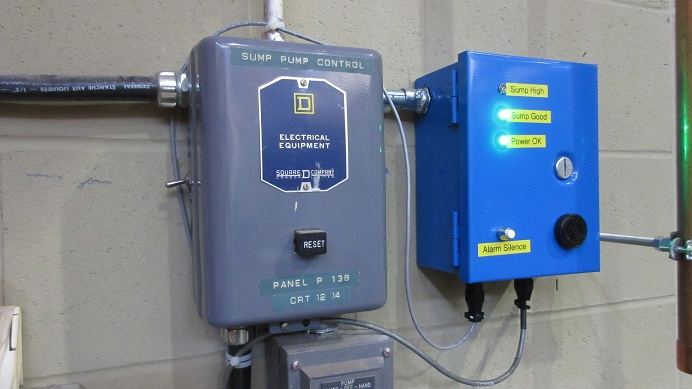
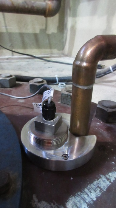
To address the deficiencies identified in E-Logs #204 and #205 the old active sump high level switch was replaced with Omega LV164SS model (316SS stem and float, 4' length, standard mount) using adaptor flange TRH1316 to mount to the top flange of the sump. A new electrical box was also installed (circuit diagram attached in PDF format). The circuit was designed by Don Jackson and wired by Travis Cave. Connection to the RCR Lab PLC was done by Dave Morris.
The switch was tested using the following procedure:
1. The switch was triggered by submerging the base in water until the float lifted. This was confirmed to be equivalent to disconnecting the CPC-4 connector for the switch from the new electrical box
2. Switch connector disconnected: Local alarm sounds in HC Lab, red "Sump High" LED light illuminates, green "Sump Good" LED turns off, RCR PLC reports high level (cannot be reset), main control room "MHESA B1 RCR1 RM 6 WARN" displays NOT OK (this will sound every 3 minutes until the RCR PLC high level alarm is reset)
3. "Alarm Silence" button pressed on new electrical box: Local alarm stops, LEDs on electrical box do not change, RCR PLC still cannot be reset
4. Switch connector reconnected: "Sump High" LED turns off, "Sump Good" LED turns on, RCR PLC can be reset
5. Power to the electrical box removed by switching off the breaker: All LEDs turn off, no alarm, RCR PLC reports high level
Pump out of water from the MHESA Lab active sump to the HC Lab active sump was tested while observing the HC Lab sump. The water entering the HC lab sump did not splash on the new switch excessively, and did not cause any false alarms.
The new system will continue to be tested annually according to the calibration schedule.
|
| Attachment 3: RH_HC_Lab_Active_Sump_High_Level_Sensor_-_Electrical_Schematic.pdf
|

|
|
215
|
Wednesday, March 15, 2017, 16:13 |
Isaac Earle | Standard Operation | Other | Active Sump | Meson Hall Hot Cell Lab Active Sump Water Released |
On March 13th in the morning the Meson Hall Hot Cell Lab active sump reached the high level sensor. The system responded as expected: high level panel warning light illuminated, siren sounded, and MCR notified via "B1 RCR1 RM6 WARN". A 1L sample was delivered to RPG for analysis. After approval, the sump was pumped out over the following two days. The procedure in Document #64834 was followed for sampling and pump-out. |
|
233
|
Thursday, March 22, 2018, 17:24 |
Isaac Earle | Standard Operation | Other | Active Sump | RH Lab active sump released |
The RH Lab active sump level reached the high limit yesterday due to an overflow of the ultrasonic cleaner in the Rad Waste Area. The sump was sampled by RPG, and after analysis the water was approved for release. The water was pumped out today. Local and MCR alarms functioned as expected. |
|
275
|
Wednesday, April 14, 2021, 14:30 |
Isaac Earle | Standard Operation | Other | Active Sump | RH Lab Active Sump pumped out |
The RH Lab Active Sump reached the high level sensor at some point overnight before the April 8th work day. Maico Dalla Valle noticed the alarm in the morning and notified RPG and myself. I also received a notification by e-mail from Vicky Hannemayer who had been contacted by Ops because of the RCR alarm.
After sampling and testing by RPG the sump contents were released under work permit C2021-04-08-5 as per the procedure in Document-64834. The approximate volume of the full sump is 7270L. |
|
299
|
Monday, August 22, 2022, 09:01 |
Adam Newsome | Standard Operation | Other | Active Sump | Active Sump Draining |
On Aug. 18, 2022, Operations informed RH group that an alarm activated for the full status of the MHESA B1 RCR1 Lab holding tank. Additionally another alarm was reported in the RH control room regarding the RH sump full (Southwest Meson Hall Extension - Remote Handling area). However, there is an alarm signal for the RH sump that was seen as OK at the MHESA Lab HMI.
Upon examining the RH active sump it was clear that the water level was in fact quite high, and the red warning light on the local control box was on.
After sampling and testing by RPG the sump contents were released under work permit C2022-08-19-3 as per the procedure in Document-64834. The approximate volume of the full sump is 7270L.
When the water level was below the warning threshold (i.e. red warning light came off, and green light indicating "sump good" came on), a request was made to the control room to reset the alarm. Operations cleared the alarm at the RCR Lab controls and retired the signal defeat that was in place in the DCR (“RCRL warn” signal was defeated).
Edit (2022-08-23): BL1A holding tank water level was checked - it is empty. |
|
306
|
Tuesday, January 03, 2023, 07:42 |
Adam Newsome | Other | Other | Active Sump | Active Sump - Level Check |
The sump level was checked by Robin Swanson on Dec. 31, 2022. It was essentially empty - see attached photo. |
| Attachment 1: 2022-12-31.jpg
|

|