| ID |
Date |
Author |
Category |
Type |
Module |
Target/Number |
Subject |
|
1592
|
Wednesday, August 02, 2017, 15:41 |
Keith C Ng | Assembly/Bench Test | Development | | | spare source tray build |
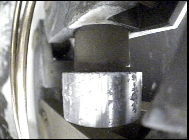
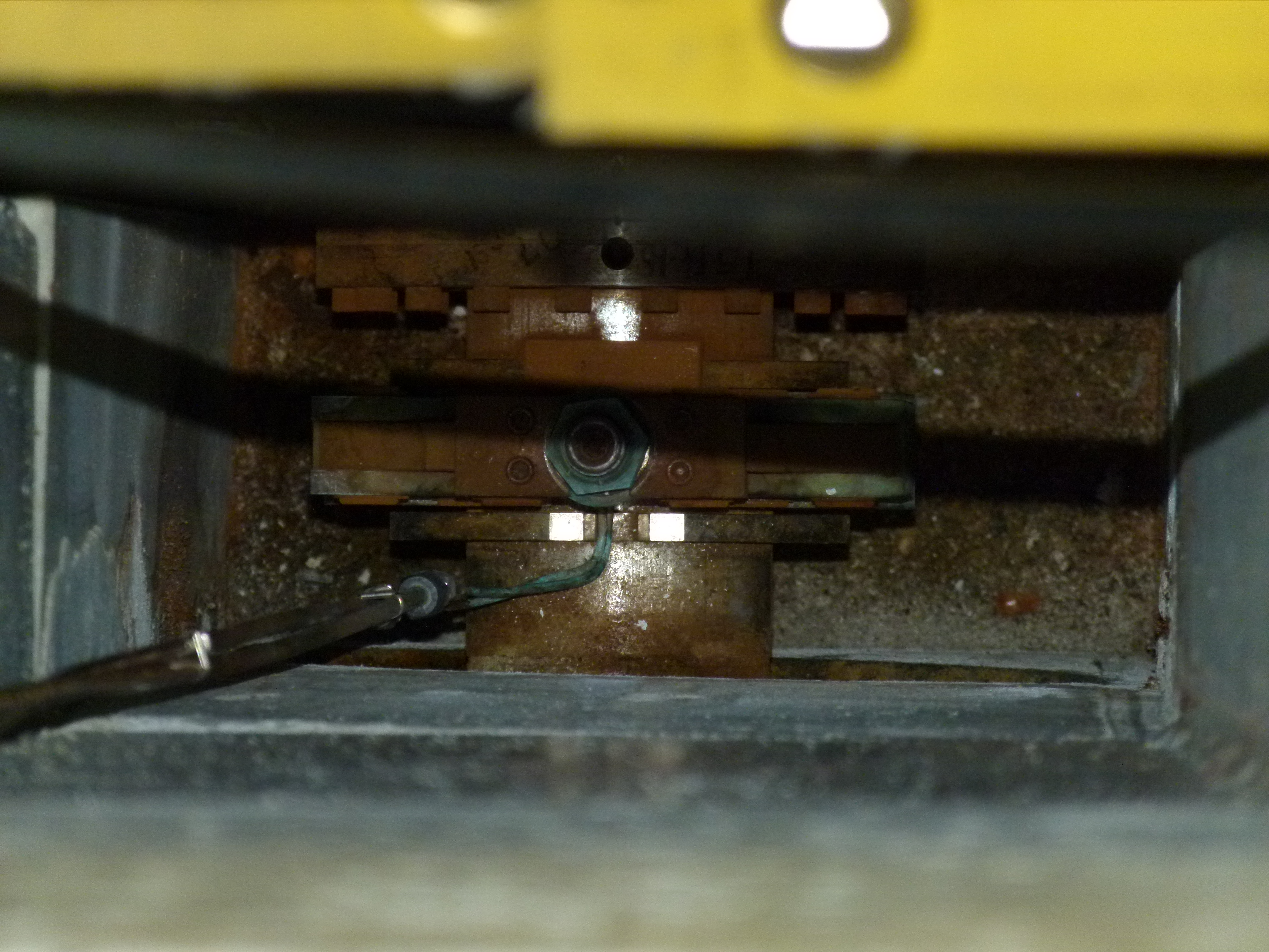
After re zeroing alignment telescope to master jig and adjusted parts into place:
Orientation: X = Left -, Right+; Y = Up +, Down -
Front wire target
X = 0.000, Y = 0.000
Rear wire target
X = 0.000, Y = +.008" (high)
All fasteners torqued to specification, steerer housing and assembly not installed yet. Weight of steerer assembly might cause rear to sag into place. Otherwise may attempt to split difference between the front and rear elements (alignment is on an angle in the horizontal vertical plane.) |
| Attachment 1: 20170802_sourcetray_RHB_8264.JPG
|

|
| Attachment 2: 20170802_sourcetray_RHB_8266.JPG
|

|
|
1640
|
Wednesday, October 11, 2017, 15:50 |
Keith C Ng | Assembly/Bench Test | Standard Operation | | | spare source tray build alignment |
Spare source tray build continued.
Initial alignment check in the morning:
- Target mounting plate target: Horizontal: .002, Vertical: -.002
- Ground electrode (bore) target, with un-clamped target: H 0.0 V -.003
- Ground electrode target (with target clamped): H: 0.0, V: .010
@14:10: sighting Master target position WRT sighting axis, calculated using the edges of the brunson target center circle edges calculated to center. Target circle is .02" in diameter.
- Master target mounted with slight finger torque.
- Front of master target, H .002 V -.002
- Rear of master target, H: 0.0 V: .005 (circle target is .020" in diameter)
- Rear of ground electrode target, H: .002, V: 0.011
@14:49: Replace mount plate target.
- Target mounting plate target: H -.001, V .001
- Ground electrode target: H .002, V .011 (rear target was rotated 90 deg from in the morning as a check)
@15:21 Steerer cone re-alignment.
- Undid the six screws holding the steerer cone and steerers to the aluminum flange and adjusted cone tip to RIB axis. The ground electrode bore was deemed not to be adjustable to the RIB axis with the current build order.
*Steerer cone assembly torque is 23 in-lbs
- Steerer cone target, H: .001, V: 0.0
- Steerer cone target, H: .002, V: .002 (after rotating target 180 degrees)
@15:30 Replaced target mounting plate target.
- Mounting plate target, H: .001, V: -0.001
Will go ahead and finish mounting components to mounting plate and final check the alignment after. |
|
1642
|
Friday, October 13, 2017, 11:14 |
Keith C Ng | Assembly/Bench Test | Standard Operation | | | source tray alignment/build |
Source tray is complete for brazing, gas line bracket is currently missing but can be made in parallel with tube bending operations.
Source tray water lines to be fabricated according to ITA6144 drawing set.
- Alignment between target mounting plate and steerer cone is holding within .002"
- Aluminum soldering jigs are installed in place of the ceramics with fasteners only torqued just past "finger tight". |
| Attachment 1: 20171013_sourcetray_P1030815.JPG
|

|
| Attachment 2: 20171013_sourcetray_P1030816.JPG
|

|
| Attachment 3: 20171013_sourcetray_P1030817.JPG
|

|
| Attachment 4: 20171013_sourcetray_P1030818.JPG
|

|
|
1703
|
Friday, April 20, 2018, 15:33 |
Keith C Ng | ITW | Repair | | | ITW beam tube repair job |
2A2 window has been removed from ITW and beamlines has removed the beamtube from the penetration. The penetration has been sealed with plastic sheeting and duct tape to maintain the ventilation depression between the 2A tunnel and the Target Pit.
Window is currently stored in a lead flask in the target hall. Window fields are 26 mSv/h OC, 1.2 mSv/h at .5m. There is a 10 uSv/h field outside the flask with the window inside it.
Clamp is currently sitting bagged in ITW Station Pit, it is quite corroded.
Tank flange was video inspected but still needs to be cleaned, currently there is a slip on dust cover over the flange to protect it.
Work will resume after the nuclear ventilation comissioning is completed.
|
| Attachment 1: 20180420_2a2beamtuberepair_P1040034.JPG
|

|
| Attachment 2: 20180420_2a2beamtuberepair_P1040030.JPG
|

|
| Attachment 3: 20180420_2a2beamtuberepair_P1040029.JPG
|

|
| Attachment 4: 20180420_2a2beamtuberepair_P1040036.JPG
|

|
|
1704
|
Friday, April 27, 2018, 15:06 |
Keith C Ng | ITW | Repair | | | ITW beam tube repair |
Vacuumed out remainder of debris from the wall penetration, removed cradle and checked condition. Down stream support bracket sees advanced stages of material loss (OBO 20-30% loss). See attached photos.
RPG reports that the removed beam tube has 15k CPM on the interior of the beam tube.
Tank flange was cleaned as per 2009 repair report, looks OK. Video capture of flange inspection attached as .zip file.
.03" shim was inserted into the clamp indexing block.
|
| Attachment 1: 20180427_2a2windowbeamline_P1040042.JPG
|

|
| Attachment 2: 20180427_2a2windowbeamline_P1040043.JPG
|

|
| Attachment 3: 20180427_2a2windowbeamline_P1040044.JPG
|

|
| Attachment 4: 20180427_2a2windowbeamline_P1040046.JPG
|

|
| Attachment 5: 20180427_2a2windowbeamline_P1040041.JPG
|

|
| Attachment 6: 2018_2a2windowinspection.zip
|
|
1705
|
Tuesday, May 01, 2018, 10:54 |
Keith C Ng | ITW | Repair | | | 2a2 window installation and beamtube repair |
Yesterday we installed the 2a2 window, the drive screw was torqued until 70 ft-lbs and we stopped, the yoke is not fully closed to its hard stop with roughly 7/8" to 3/4" still to go. Similar to identical conditions to 2a3 beamline window install, see https://elog.triumf.ca/TIS/RH-ISAC/647 for that install. Otherwise clamp looks centered and installed correctly.
Concerns with the cooling lines for the window WRT to the base of the shielding plug: There is no jog bend indicated on drawings for the transition of the window cooling lines from beamline center to the corner of the shield plug penetration. See photo for cooling line position on initial removal of shielding plug. It was decided to not add a jog for the shield plug and to carefully reinsert it being mindful of the cooling lines. The shielding plug has a chamfer on the corner to allow the cooling lines to be routed to the top.
A new beam tube cradle is being manufactured where the old one will removed and the new one swapped with the beam tube in situ. Both sides of the window still need to be leak checked. |
|
1723
|
Thursday, May 24, 2018, 15:19 |
Keith C Ng | Assembly/Bench Test | Repair | TM2 | | tm 2 source tray build |
Attached alignment check notes after brazing and fabrication.
First page lower half shows establishment of baseline using master jig
Second page top half shows the alignment of the target mounting plate jig and the steerer cone aperture.
Second page bottom half shows alignment of the master target jig. Master target jig needed the 9 pin and heat shield locating features removed to seat the target correctly.
Overall, source tray assembly sits .006" high on average (min .003", max .010"), .003" to the left with respect to ion beam axis. |
| Attachment 1: 20180524_alignmentcheckresults.pdf
|

|
|
2371
|
Monday, October 03, 2022, 14:28 |
Keith C Ng | Assembly/Bench Test | Maintenance | | | ITA2826 rev E assembly |
A fully built steerer sub assembly ITA2826 revision E was boxed and sealed and put on rack storage in ISAC B2 South Hot Cell area. It is contained in a blue bin and green tag.
It is advised if this assembly is used, it should be inspected for damage before using in a source tray. |
|
2549
|
Wednesday, March 13, 2024, 11:12 |
Keith C Ng | Assembly/Bench Test | Repair | TM3 | | optics tray for tm3 |
Alignment notes attached for the optics tray for the refurbished tm3 with the new service and source tray.
*Note: Drive screw bracket sheared off during alignment check with source tray. The drive bracket was replaced. The optics tray was re checked. The front element was .015 to left and centered u/d. The rear element remained the same. The center element could not be checked to do the assembly. |
| Attachment 1: 20240313_optics_tray_alignment_notes.pdf
|


|
|
2471
|
Thursday, August 03, 2023, 12:24 |
Jason Zhang | Crane | Development | | | Cleanup of camera installation on target hall crane, installation of replacement laser |
The cleanup of the ISAC Target Hall crane and installation of the new SICK laser which replaced the IBEO laser for the EW crane position was completed on Aug 03 2023.
The clean up tasks which were completed: (Removal of tape viewing camera, Removal of tape, Installation of extension cord, Consolidation of power supplies for the lasers and removal of old laser)
Currently power bar is still present to act as an extension cable. This will be removed when 2m extension cord is made and put in next target exchange cycle.
The installation and testing of new SICK Laser:
1. Calibration points were taken at the 4 corner limits of the crane. North South and East West positions were recorded.
2. Crane was parked at the ladder access position and mounting bracket was machined and installed.
3. A new cable was made and installed for the SICK laser. Continuity test was performed from the control room and crane to ensure pinout of the laser worked with existing serial communication setup in the control room PC.
4. The feedback values from the new SICK laser and old IBEO laser were compared to determine that a calibration offset of 0.06m was needed in the Laser Position Feedback program.
5. Laser Position Feedback program was re-compiled to communicate with 2x SICK lasers with the calibration offset value included in the EW feedback position. (Laser Crane PositionDlg.cpp)
6. Calibration points were taken at the 4 corner limits of the crane again with the new Laser. North South and East West positions were recorded.

There was less than 0.1% variance between the new laser and old laser which is well within the tolerance of the lasers themselves. It can be determined that it was properly calibrated.
|
| Attachment 1: LaserProgramCalibrationLocation.png
|

|
| Attachment 2: SICK_Laser_Upgrade_Calibration.xlsx
|
| Attachment 3: Installation_IMG.png
|

|
|
2819
|
Friday, June 20, 2025, 10:38 |
Jason Zhang | Spent Target Vault | Maintenance | | | Annual Inspection of Main and Mini Storage Vaults |
The annual inspection of the main storage vault and mini storage vault was performed on 2025-06-20.
The alignment of the main storage vault door was checked and confirmed to be fixed. The paint was checked to see if there was any visible marks which there were none.
The following was also checked:
- Cabling and cable management (note: the emergency override mechanism's aircraft cable showed signs of fraying. Recommended to keep and eye on it and potentially replace in the future)
- Connectors
- Controls box - external connectors and wiring
- Limit switches - wiring, mounting (note: The opened-limit switch for the mini storage vault was shifted a 5mm to accommodate the addition of a rubber bumper for the motor. It was noted that the motor was bumping into the SMP due to inertia of the mini vault door. Testing confirmed operation after the modifications.)
- Motor visual check (note: The drive chain on the main storage vault had excessive slack so the motor was re-aligned and the chain tightened. The main storage vault was not opened this inspection so testing of the opening and closing is required.)
- Drive wheels visual check
- Drive track visual check
- Bearings visual check (note: The bearings on the main storage vault were re-greased)
- Miscellaneous fasteners visual check
Photos can be found in:
G:\remote handling\Facilities and Projects\ISAC\Storage Vault\Inspections
G:\remote handling\Facilities and Projects\ISAC\Mini Storage Vault\Inspections
The inspection was generally successful. No areas of concern. Regular inspection will resume next year. |
| Attachment 1: Fray.jpg
|

|
|
2820
|
Friday, June 20, 2025, 10:46 |
Jason Zhang | Safe Module Parking | Maintenance | | | Annual electrical and mechanical inspection of Safe Module Parking |
An annual electrical and mechanical inspection was performed on the SMP on 2025-06-20. The following items were checked:
- Check condition of wiring for physical/radiation/UV damage
- OK, no signs of significant damage
- Check for cable tray debris or damage
- Check inside control panel: components and wiring, labeling
- Labeling intact, components in good condition
- Misc. random wires pulled to check... OK
- Check connectors for damage
- Check pendant for damage and verify labeling intact
- Lid open/close test
- Lid was opened and close multiple times - smooth operation, no concern
- Lid close logic was checked - OK
- Vessel rotation and limit switch check
- Both CW and CCW limits were checked, functioning
- No concern on rotation - chain drive, rotary limit switch, and cable reel all functioning normally
- Inspect tensioners
- Visual inspection
- Lid Bearings
- Noticed a missing grease nipple so a new one was installed.
- Applied grease to the bearings although it may not be necessary due to the movements allowed in the lid mechanism.
Overall the inspection was successful. |
|
446
|
Tuesday, September 10, 2013, 12:11 |
Isaac Earle | South Hot-Cell | Repair | TM3 | | Module side heat shield water block polishing and blank-off installation |
The sealing surfaces of the module side heat shield water block were polished on September 9th in the morning using Chad's polishing tool with the following attachments:
- Scotchbrite pads (30 seconds) (after this step indium material from the previous seal was no longer visible on the sealing surface)
- 2000 grit sandpaper (30 seconds)
- Felt material with isopropanol (30 seconds)
- Lint free pad (30 seconds)
After the final step the surface was rinsed with isopropanol and air dried using canned air. The water block blank-off was then installed with the manipulators, tightened until snug using the air ratchet, then tightened an additional 1/4 turn while the water block was gripped firmly using one manipulator. The seal was leak checked and passed successfully. |
|
894
|
Tuesday, April 21, 2015, 17:14 |
Isaac Earle | South Hot-Cell | Standard Operation | TM1 | UC#12 | UC#12 Installed in TM1 |
On Friday April 17th, UC#12 target was installed in TM1. One of the copper water lines was bent slightly as the target was lifted into the module which caused ~15 minute delay due to difficulty getting the VCR nut threads to engage. Other than this the install went smoothly.
During replacement of the containment box panel two of the threaded holes were found to be stripped. One on the top at the center, the other in the bottom right corner. These two holes were left without fasteners (see attached photo). It is unknown at this time whether these holes were already stripped, or if they were stripped during this installation. |
| Attachment 1: IMG_4836.JPG
|

|
| Attachment 2: IMG_4833.JPG
|

|
|
952
|
Friday, June 19, 2015, 09:37 |
Isaac Earle | South Hot-Cell | Repair | TM2 | | TM2 Source Tray Installation - June 18, 2015 |
The following work was done on June 18 2015:
- Finished cleaning and polishing all water blocks on module side (white felt with isopropyl, then buffing material with isopropyl, then canned air). Heat shield waterblock re-done because water marks visible (white scotchbrite, white felt w/ isopropyl, buffing material w/ isopropyl, then canned air). All surfaces looked very good, no lint or scratches visible.
- Tray installed using installation jig (jig was very difficult to slide on hot cell table). Window circuit waterline bracket tube retaining screws had to be removed for the sourcetray to clear the module frame. Optics tray locating mushroom on source tray rubbed against the module side waterblock jig and was pushed past. Gas lines were held clear of the source tray with the manipulator as the it went in. The nut on the source tray side water block guide pin had to be loosened to facilitate complete insertion of the source tray.
- Connection of waterblocks for circuits D, C, B, A, Febiad Coil 2 were done in the sequence listed with no issues
- Extraction electrode and heat shield water blocks could not be done up initially because the locking tabs could not be undone (interference with module side jig bracket)
- Ground electrode waterblock connected without issue
- Window waterblock attempted: screws would not engage
- Febiad coil 1 negative waterblock source tray side locking tab had to be re-inserted into block, then waterblock was connected
- Febiad coil 1 positive connected without issue (failed initially due to shorter screw)
- Mounting support plate waterblock alignment pins did not engage initially, rotated source tray side waterblock using polishing tool. Then was connected without issue.
- Extraction electrode waterblock revisited: pulled together with 1-5/8" screw, then connected (with 1-3/8" screws in both holes as per ITA6144)
- Heat shield waterblock revisited: installed without issue (as the jig had been pulled together by the previous step)
- Attempted window water block again. Right side manipulator wrist tong cable broke while using camera. Waterblock could not be connected (holes look concentric, pins engaged, blocks together and almost flush)
- All waterblocks except window waterblock torqued (tool did not slip properly, so torque will be re-checked)
Plan for Friday June 19:
- Put blank-offs and various fasteners in hot cell through tool port
- Check torque of all waterblocks with dial torque wrench
- Attempt window water line again with different fasteners (non-blunt start), try removing both sides of waterblock alignment jigs
- Install blank-offs on window and heat shield lines (VCRs)
- Perform preliminary leak check |
|
1032
|
Monday, August 10, 2015, 14:07 |
Isaac Earle | South Hot-Cell | Repair | TM2 | | TM2 Containment Box Removed |
The containment box was taken off TM2 in preparation for installation of a new coil line isolator.
ITA6272 and ITA6273 have been received from the Scintillator Shop. ITA6274 should be ready by the end of today. |
|
1221
|
Wednesday, May 04, 2016, 11:14 |
Isaac Earle | North Hot-Cell | Development | | | North Hot Cell Scope Decision |
A meeting was held on May 4, 2016 to determine the scope of the North Hot Cell project. The following was agreed upon by those in attendance:
The NHC will be a designated target change hot cell. It will be capable of performing all routine target operations (target removal/installation, leak check, electrical check, video inspection, post irradiation examination, target waste packaging and removal) using the same method currently used in the south hot cell. Provisions will be included for the ability to perform target waste separation in the future unless a significant obstacle is encountered in which case the meeting attendees will be consulted. Target waste separation involves separating the internal target heater from the target heat shield, then combining multiple target heaters in a single F-308 shipment. Neither an inert gas atmosphere nor a double-door waste transfer system will be part of the NHC scope.
The following people were in attendance: Bob Laxdal, Anders Mjos, Don Jackson, Joe Mildenberger, Friedhelm Ames, Alex Gottberg, Grant Minor, Yasmine Saboui, Peter Kunz
The following people were invited, but were unable to attend: Chad Fisher, Pierre Bricault
The project will begin immediately, with Isaac Earle as the project leader. The first steps will be to submit a Project Initiation Sheet, then to write and release the Requirements Specification document. |
|
1294
|
Friday, July 29, 2016, 14:27 |
Isaac Earle | North Hot-Cell | Development | | | North Hot Cell Measurements & Cleanup |
The North Hot Cell was accessed today via the Ante Room for inspection, measurements, and clean-up. There were no modules in the SHC or TCS, and no spent targets in the SHC. Under these conditions the maximum field in the NHC was approximately 2μSv/hr. The inside of the cell was cleaned and swept, followed by a floor swipe to check for contamination (none found). All areas of the ante room floor were also swiped: no contamination found.
The following measurements were taken in the NHC for comparison with the Soldiworks model:
SHC/NHC feedthrough panel fastener size: 1/4"-20, 1/2" long
NHC west wall to east edge of SEG block: 33-1/4" on south side, 33" on north side
NHC west wall to furthest extent of TCS (IRH1170): 40"
NHC west wall to wall indentation for viewing window: 46-7/8"
NHC west wall to end of existing ventilation duct: 4-1/8"
|
|
1307
|
Friday, August 05, 2016, 14:13 |
Isaac Earle | North Hot-Cell | Development | | | Preparations for NHC Ventilation Test |
A hole was drilled in the NHC exhaust duct in the east end of the target hall above the hatch to the Ante Room. This will be used for measuring NHC exhaust flow rate with a thermal anemometer. The hole was tapped and plugged with an NPT tap.
Flow was measured in the existing hole in the SHC exhaust duct in approximately the same location. Flow velocity was measured to be 1415 ft/min with the lid on the SHC. Using duct ID 7.75", and assuming the average flow velocity is 90% of the flow at duct center, the flow rate was found to be 417cfm. We will attempt to match this figure for the NHC when the ventilation tests are performed. The tests have been scheduled for the maintenance day on Tuesday August 9th.
The anemometer probe and SHC test port plug were checked for contamination: none found. |
|
1315
|
Wednesday, August 10, 2016, 14:38 |
Isaac Earle | North Hot-Cell | Development | | | North Hot Cell Ventilation Test Results |
Testing was performed on August 9th on the ISAC nuclear ventilation system to determine if the existing ventilation system can achieve the required cell depressions for both SHC and NHC under all expected configurations and if a proposed modification to the DDC control system can provide acceptable stability and response time for the system. The proposed control system observes the lower of the SHC depression or the NHC depression + 10% (to avoid stability issues), and adjusts the dampers to try to achieve 250Pa (1.00" WC) depression in the area it is observing. With the proposed control system the SHC and NHC dampers are programmed to be at the same position, but can be tuned with a bias between them if required to achieve all ventilation requirements. The NHC and SHC dampers are programmed with a limit at 90% of the fully-open position. There is a damper in the ducting system in the section of duct after the SHC and NHC legs join together; this is set at 50% open, and was not adjusted during the the tests. Test summary and results are listed below:
1. Prior to switching to SHC+NHC control mode, the flow rate and depression of the SHC was measured with the lid on: 266Pa cell depression, damper 47% open, duct flow 417cfm. The lid was opened and the measurements repeated: 35Pa, damper 90% open, duct flow 630cfm (results in 83ft/min, 0.42m/s average flow velocity across HC module opening)
2. The control system was switched to the new SHC+NHC single control loop system. Measurements were taken with both hot cell lids closed. SHC: 246Pa, damper 72% open, 350cfm flow rate. NHC: 257Pa, damper 72% open, 510cfm flow rate. The ventilation fan speed was then increased from 53Hz to 57Hz (maximum speed is 60Hz). Measurements were taken with both hot cell lids closed. SHC: 257Pa, damper 51% open, 353cfm flow rate. NHC: 257Pa, damper 51% open, 515cfm flow rate.
3. The SHC module port lid was opened and the NHC lid left closed. SHC: 37Pa, damper 90% open, 462cfm (results in 61ft/min, 0.31m/s average flow velocity across HC module opening). NHC: 249Pa, damper 90% open, 551cfm.
4. The NHC module port lid was opened and the SHC lid closed. SHC: 203Pa, damper 90%, 360cfm. NHC: 33Pa, damper 90%, 648cfm (results in 85ft/min, 0.44m/s average flow velocity across HC module opening). The fan speed was then increased to 60Hz (max speed) to see if the depression setpoint for the SHC could be achieved in this configuration. SHC: 231Pa, damper 90%, 389cfm. NHC: 29Pa, damper 90%, 705cfm (results in 93ft/min, 0.47m/s average flow velocity across HC module opening)
5. Both SHC and NHC module port lids were opened and the fan was left at 60Hz. SHC: 31Pa, damper 90%, 448cfm (results in 59ft/min, 0.30m/s average flow velocity across HC module opening). NHC: 29Pa, 90% damper, 669cfm (results in 88ft/min, 0.45m/s average flow velocity across HC module opening)
For all tests the control system arrived at a stable depression value in less than 5 minutes, and thereafter exhibited only minor fluctuations.
It was observed that when the fan speed was increased to 57Hz, and for the duration of the tests, there was negligible change in the depression and damper positions for the mass separator room and target pit area.
The HEPA filter in the SHC leg of ducting has not been changed since commissioning of the facility (~15 years), and the SHC charcoal filters have not been changed since installation approximately 5 years ago. The SHC pre-fitler located inside the cell was changed in January 2016. When these are changed (which should be done before commissioning of the NHC ventilation system), the difference between SHC and NHC flow rates should decrease, and the SHC depression with NHC open should increase (likely up to the 250Pa setpoint).
Conclusion: The new SHC+NHC single control loop system effectively controls the system under all conditions tested. The existing ventilation system achieved the required NHC depression (250Pa, from RS 50, Document #131915) with both cells closed, and with SHC open only. The same depression for SHC with both cells closed was achieved with both cells closed, but only reached 231Pa w/ NHC open (203Pa at 57Hz fan speed). It is expected that 250Pa can be easily achieved in the final system because the NHC will be better sealed than in its current condition, the damper in the shared SHC/NHC leg can be opened further, there will be greater flow through the SHC leg after changing the HEPA and charcoal filters, and the system can be tuned to better balance the SHC and NHC flow rates. RS51 states "the ventilation system should maintain an average air flow velocity of 0.5m/s across the opening into the hot cell". This is almost achieved with the NHC open, but SHC only had 0.3m/s average flow velocity. It should be possible to increase both to > 0.5m/s by further opening the shared leg damper and tuning the system to have more balanced flow rates. At the very least, both SHC and NHC should have > 0.42m/s average flow velocity to match what is currently achieved in SHC only mode (measured in test step #1), which to date has not allowed contamination to escape out the top of the hot cell. Depending on what flow velocity is deemed acceptable, after commissioning it may be possible to have both the SHC and NHC open concurrently based on the results of Test 5. At the time of commissioning, the SHC/NHC damper bias and NHC air inlet damper should both be tuned to achieve as similar depression and flow rate conditions as possible for both cells, and to meet all requirements in the RS document.
Notes:
Duct flow rate was calculated assuming that measured flow velocity at the center of the duct is 90% of average duct velocity. The duct ID at the sample location is 7.75", the hot cell opening size used for SHC and NHC module opening flow velocity calculations was 33" x 33".
Duct flow velocity measurements were taken using a thermal anemometer (Model number: 9555-P, Serial number: 9555:1108059 Rev. 2.11.0, Last calibrated by Rob Walker on April 29, 2016).
After completion of the tests the system was restored to it's original configuration and the ISAC target hall was swiped for contamination: none found. No EF12 trips occurred during these tests. |