| ID |
Date |
Author |
Category |
Type |
Module |
Target/Number |
Subject |
|
2536
|
Friday, January 26, 2024, 16:48 |
Carla Babcock | South Hot-Cell | Standard Operation | TM4 | UC43 | UCx#43 PIE | UCx#43 PIE was done in the SHC. As expected based on electrical measurements, the target container was broken on the right side and came off easily. Despite all the black stuff seen on the containment box and source tray, the inside of the heat shield was very clean. Checked if the Re foil was curled in and didn't see anything. Looked fine other than the broken container. |
|
2541
|
Monday, February 12, 2024, 18:44 |
Carla Babcock | ITW | Maintenance | | | ITW annual HV testing | ITW was set up for HV testing - water is running and at a high resistivity due to injected N. Einzel lens is attached to ground. Everything else is as normal. The module plug is in so no vacuum bypasses were needed. Very easy to ramp to 60kV. Sat at 60 for about 1.5hrs with maybe 1 spark (hard to say from the strip tool data). Current draw was about 176uA. Data dumped as isac/data/ITW_HVtesting_shutdown2024 |
|
2545
|
Thursday, February 15, 2024, 17:40 |
Carla Babcock | ITE | Standard Operation | | | ITE annual HV testing | ITE was set up for HV tests - this time the module plug was not in so the BIAS and EE had to be bypassed. NOTE: ITE:BIASPLC must also be bypassed for this to work. Currently it is located on the vacuum bypasses page, but may be changed to the optics page soon.
ITE was ramped to 60kV in steps of 1kV easily. It sat at 60 for about 1.5 hours with a current draw around 173uA. It was not entirely stable though, and appears to have sparked many times. None of them seemed very large, but hard to tell.
When ramping down, current dropped quickly with the first couple steps. Data saved as isac/data/ITE_HVtesting_shutdown2024 |
|
2566
|
Tuesday, April 23, 2024, 17:34 |
Carla Babcock | South Hot-Cell | Repair | TM3 | | TM3 wire pulling | Wires were pulled in TM3 and service cap was closed up again:
Einzel lens wire (30kV kapton), routed in the pumping duct and attached with #10 ring tongue to EZL feedthrough in service cap
4 steerer wires, routed in th pumping duct and attached with push on connectors to the 4 SHV feedthroughs on the module side panel. Coax grounding sheath is cut back by about 3cm.
Multipin cable bundle #1, routed through the left cable tube in the service tray then along the heat shield water lines (with PEEK zip ties) to feedthrough A.
Multipin cable bundle #2, routed through the right cable tube in the service tray then along the heat shield water lines (with PEEK zip ties) to feedthrough B. This bundle contains the EE wire as well, which was branched out after exiting the service tray and routed along the gas lines to the EE feedthough. It was attached with a smaller (size?) ring tongue to the EE feedthrough. Do not use this wire again, very fragile. Use the Accuglass 30kV wire instead.
The multipin wires touch the back of the water blocks in the source tray (same as in MT2/4, so far no issues with that) and they also touch the COIL lines in the service cap.
The EZL and steerer wires are routed along the floor of the service cap.
Due to the difficulty of the installation, there is no metal braid over the multipin bundles in the service cap.
Photos here : https://triumfoffice365-my.sharepoint.com/:f:/g/personal/cbabcock_triumf_ca/EslWNUST-UJKh1s8jjxWG6EBpLQEnWxgV4v-NvR4ZJjlOQ?e=Mw5vvI |
|
2581
|
Thursday, May 02, 2024, 18:48 |
Carla Babcock | ITW | Standard Operation | | | ITW cage setup | ITW gas lines pumped down to 2e-3Torr on leak detector with leak rate in the low e-7 atm-cc/s. Gas bottles opened at 3psi and labels in epics changed to reflect correct setup. switch box set to cathode mode, checked that anode wire was at HV common.
note ballast is removed from ITW now to be used in ITE so that line is blanked off. |
|
2591
|
Tuesday, May 14, 2024, 15:27 |
Carla Babcock | ITE | Development | TM3 | UCx#44 | TM3 conditioning and testing in ITE | Tuesday, May 14, 2024, 10:26 :
Ramping up bias/EE/EL on ITE - will see if the HV cage in the pit can hold 60kV or not.
At around 50kV the bias read current starts to get jumpy. Doesn't look like its an issue for the voltage, but definitely instability increases.
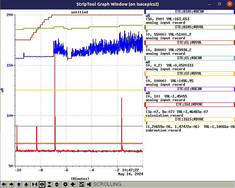
Occasional sparks seem to increase the EL current significantly...
David heard some sparks in the target hall. Looks like from heat shield feed through to the top of the cage. Several sparks heard in the TH also changed the einzel lens draw current significantly. These feethroughs are not far from each other so could be related.
Apparently the sparking also tripped off all the optics and heaters in ITW, by changing the state of the water flow interlock. Interesting and not seen ever before. Will test again with the cage off, rather than risk tripping ITW again.
Tried ramping up the voltage on just the EE. Seems the limit is 7kV - at that level it gets sparky and unstable. Should be investigated (should hold 10kV) but not critical for module function.
Wednesday, May 15, 2024, 10:05 :
HV cover was removed this morning and the MAA was locked out.
Started ramping things up, was very easy until around 58kV. At 59.5kV a spark tripped off the EL. Canbus controller had to be power cycled to fix it. Bias current is much more stable in this configuration.
Ramped up again while listening from the TH to see if it was sparking outside. Went slowly to 60kV (left EL at 29kV) and didn't see any outside sparks in the first 10 mins, couple sparks in vacuum. But after 15 mins a spark seems to have fried the EL canbus card. We were not in the TH so not sure if it was on the outside or not.
After 2 hours a spark tripped off both ITE and ITW. Looks like it makes a water interlock go bad momentarily, but after the trip the interlocks seem fine.
Tuesday, May 28, 2024, 16:41
Running TM3 at any voltage in ITE produces fairly destructive sparks. There are not many but so far they have tripped off all optics in ITW, the water flow interlocks (later forced on to prevent this), the EL (generally comes back but killed the canbus card once), destroyed two vacuum gauge controllers, and may have contributed to the cathode short on ITE-TM3-UC44-LP-FEBIAD.
The conditioning process seems to go as planned, but the occassional inevitable spark still trips things, which is making it difficult to run stable.
Will continue with regular HV conditioning to see if this helps. Control over the current limit on the ITE:BIAS supply would also help, but seems a complicated thing to add according to Roberto.
TM3 sat fine at 53kV overnight and at 58kV for several hours. The EZL trips off maybe once every 2-3hrs or so, which is not ideal but liveable. This was with the TGHT and CHT power supplies forced, so not sure if we would know if they would have tripped...
CONCLUSIONS:
- TM3 has been commissioned for beam delivery after one week of delivery of UF to TITAN using a FEBIAD ion source in anode bias mode. Cathode mode was also used, so all functionality of the target except IGLIS current/voltage delivery through the mutlipin has been tested successfully.
- TM3 still requires commissioning at high voltage with protons to be considered fully commissioned, this will be done July 2 2024 due to problems with the cyclotron.
|
|
2604
|
Tuesday, June 04, 2024, 11:44 |
Carla Babcock | South Hot-Cell | Development | | empty LP FEBIAD | investigation of cathode short on empty LP FEBIAD | On May 30 Aaron, Chad and I removed the empty LP FEBIAD target from the SHC into the anteroom to attempt to find out the source of the cathode short observed online. The behaviour online was that a connection of several hundred ohms was preventing the cathode from being biased. The resistance was still enough to allow us to run in anode mode, which is what we did. I am not sure where the cathode short came from but there was significant sparking on this module when ops conditioned it (destroyed the gmov of the COIL power supply and the electronics for anode/cathode switching) and we have seen this cause cathode shorts before. The shorted behaviour did not go away when the target was cooled down, so I assume it was permanent damage to one of the insulators. This would be either the support insulator, the trident insulator, the gas line insulator or one of the tube retainer insulators.
Since the target didn't see protons, we decided to take it out of the hot cell and disassemble it to find which insulator was broken. Unfortunately, it appeared totally fine outside of the hot cell, no shorts could be found. We disassembled it anyway to look for issues but all we saw was a heat mark on the copper plates covering the coil, underneat the target (see attachment). We even shook the target quite a bit, and didn't produce a short.
Maybe there was a trace created on one insulator by the sparking, which oxidized when exposed to air and became insulating again? We didn't see anything obvious on the insulators, but I'm not sure if we would expect to.
No conclusions from this work. |
|
2613
|
Friday, June 14, 2024, 16:04 |
Carla Babcock | ITW | Repair | TM4 | UC#45 | Replaced and reinstalled electronics in ITW cage | ITW has been behaving badly at higher voltages recently, even without protons on. I conditioned it up to 50kV with heaters off in the TCS and it was fine. But when I tried to do the same with heaters on in the station, it was quite sparky and it kept tripping the TGHT/TBHT. I went to 49kV where it was unstable, then lowered to 48kV where it looked fine for 30mins. But even operating at 40kV, it tripped the heaters several times. The TBHT voltage came back lower than before on the last trip, so I am getting worried about it.
I decided to make sure all the electronic spark protection was ok in the faraday cage. There is a resistor/gmov combination across the terminals of each TGHT/TBHT in which Tomislav replaced the gmovs for me because his tester did not work at those low voltages, so we couldnt see if they were broken. The electronics diagram called for 18V gmovs, the replacements are 22V because that's all we have.
We also tested and re-installed the capacitor-gdt-resistor combinations that John installed last year from TGHT/TBHT bubars to HV common. I originally removed them because we couldn't bias a FEBIAD with them on - this still has to be investigated. The measured values are 0.148uF, 90kOhms and a breakdown voltage on the gdt of 410-450V.
Hopefully this prevents sparking the power supplies off.
Sunday, June 16, 2024, 07:03 : power supplies have not tripped off since electronics repair. See data/TM4sparkingbehaviour_June152024.dat for sparking frequency over ~10hrs of protons (5-14uA). >14 sparks during this time (14 captured by PLC when voltage dropped, many more current peaks). |
|
2615
|
Monday, June 17, 2024, 17:24 |
Carla Babcock | ITE | Development | TM3 | UCx#44 | Status of gas system prototype in ITE | A new gas system for FEBIAD operation was installed in ITE to enable us to use a calibrated leak which is attached to the target heat shield. This will allow us to control the quantity and purity of the gas going into the system, and to switch quickly between gasese and pressures.
The schematic of the system is attached. The use of the ballast container is likely not needed - it was originally included in case we want to run the system at pressures greater than 1 ATM. The roughing pump inlet limit is 1ATM, so it was envisaged to used the ballast container to reduce the pressure to that level or below before opening the system to the pump. But since it has been difficult to commission the system over 1ATM and this opens the door to several concerns about gas leakage, it was deemed better to keep operation below 1 ATM. This tank will likely be removed.
The storage tank was implemented because we are not sure if irradiated gases will be pulled out of the target lines when we pump on them, and so this was devised as a way to test that. The alternative is to have the exhaust of this pump go directly into nuclear ventilation by way of a plastic tube leaving the faraday cage, however this solution is also quite some work to implement. So the consensus was to start with the storage tank and sample it several times to understand what sorts of radioactivity we are dealing with, then make a decision about future operations.
This system has been tested offline using the development target UCx#44 and appears to work well. Unfortunately there were no protons available for this beam time so the gas sampling part of the system was not tested.
The operation of the rest of the system worked reasonably well. Beam disappeared when pumping out the lines and reappeared when re-opening the gas bottle. It seems that the storage container can be used to pump out the lines about 7 times before it gets up to around atmosphere, as was estimated based on volume. The pump can get the lines down to about 250mTorr as read by the pressure gauge DG2 on the module top, given about 30mins of pumping.
We did have some issue with the gauges, HV sparks destroyed both controllers and so we were unable to monitor pressures as we would have liked. It is possible one gauge itself is broken as well, to be investigated.
It may be that the gas leak we used was too small, but the idea of changing the pressure on the module by changing the needle valve didn't seem to work. This is not sure since we didn't have a reading on the pressure, but watching the ion beam as you turn the gas back on seemed quite binary. You would see no change until you had the needle valve fully open. This may be different with a larger leak, since this leak required about 1ATM in the lines to see anything. It is still not clear why this behaviour was different than the tests at the test stand, in which 0.5ATM of upstream pressure produced about 2nA of beam.
This system is considered a prototype and is not turned over to ops for operation. Further commissioning is required. |
|
2622
|
Monday, June 24, 2024, 14:37 |
Carla Babcock | South Hot-Cell | Development | TM3 | UCx#44 | Inspection of TM3 and UCx#44 after no-protons run | TM3 and UCx#44 ran in ITE but issues with the cyclotron prevented proton beam delivery. Nonetheless, the target was heated and provided stable beam to TITAN as well as for tuning and some tests.
Results of inspection of TM3 module after run:
The module looked pretty good. There were no marks on the polished surface of the containment box, next to the water blocks, that were visible. But we didn't remove the box, only looked with the camera and it was visible by turning the module. So some things may have been hidden. There were some black marks on the door, near the bolts that hold in the handle (see attachment). This seems a very unlikely spot for sparking as the fields should be considerably lower than at the target handles, lower down. Maybe the spots are from oil left on the door that had a chemical reaction? There is one very faint matching spot on the top of the copper trident connector, but it doesn't look much like a spark mark. The other two marks have no corresponding mark on the source tray. There were no marks on the ground electrode, or anywhere else on the source tray. There was a scuff on one of the trapezoidal insulators, but it could have happened during installation.
Results of inspection of the target after run:
The FEBIAD target developed the same cathode short we have seen on almost every FEBIAD we run online - a high resistance short from cathode to HVC that prevents voltage on the cathode. This time the short remained after cooling the target, and David measured 208kOhms with the ohmmeter on the module top (11kOhms with the megger). We used a multimeter in the hot cell to test after the target had been dismounted and we found no short. So it must be related to either the position of the target (upright vs face down) or time (a conductive trace on an insulator oxidizes and becomes non-conductive again) or some pressure/shaking during the de-installation.
There weren't many marks on the target - a faint mark near where the faint mark on the copper trident was observed, some marks on the EE which had no counterparts on the ground electrode. See pictures. |
|
2630
|
Thursday, July 04, 2024, 01:20 |
Carla Babcock | ITE | Development | TM3 | SiC#46 | TM3 conditioning with protons | Initial Summary:
TM3 sparking behaviour in ITE has been very disruptive both with and without protons. Protons are at 60uA, target heater at 540A. Max voltage achieved so far is 51kV, limited by time and a current limit on the BIAS supply.
The ITE:EL trips off every couple of minutes. Just needs to be restarted. Mike investigated and found that the trip is happening inside the power supply, then a moment later the canbus is defining the supply off when it cant get it to respond. Trip frequency decreased over time but still disruptive.
All the waterflow signals, including ones controlled in the cyclotron system, were tripping off regularly. These have all been forced, then we implemented a 5s delay in the ISAC waterflow interlocks. This seems to have solved the issue.
The ITE:BIAS supply has also been limited at 500uA instead of 5mA. Probably something hardcoded into the canbus - this was fixed by Keiko and the hardcode limit was set to 20%(?) of 5mA.
TM3 has been very sparky, even at low voltages. I can't understand why. A new ground path would be explicable but the excessive sparking is difficult to understand.
Possible avenues:
- make sure the module outer surface is connected through a copper sheet to the sheet on the wall.
- check that special ground still grounds all the gnd power supplies in the electrical room - this I checked but some of the grounds are connected through wires instead of sheets, this can be improved.
- try running the module with only HV hooked up and nothing else.
- try running TM3 in ITW.
- Search work permits and shutdown jobs for any changes made to the system that could affect this.
- hope there is a software solution for the EL problem, or start moving towards PLC control - no software solution because the canbus card is only reacting to the power supply refusing to turn on, so it seems the issue originates in the PSU. Moving to PLC is possible but may not help and increases the risk of frying the PLC module.
- Add a spark gap or limiting resistor to the EL somewhere. Resistor only helpful if the EL itself is sparking. Difficult to find a spot for the spark gap.
- Get a bipolar supply that can sink the current of a spark and replace the EL supply. - Tomislav doesn't seem to think this is viable.
- Add protection on the controls cables.
Spark recording:
60uA/50kV/540A July 3 02:30 - 05:30 : average of 50 sparks per hour. data file https://isacwserv.triumf.ca/onlylocal/isacdata/ITE_TM3_SiC46_HVConditioning_2_20240704
60uA/32kV/540A July 3 19:15 - July 3 21:45 : average of 8.4 sparks per hour. data file https://isacwserv.triumf.ca/onlylocal/isacdata/ITE_TM3_SiC46_HPSIS_HVConditioning_20240704
50uA/42.8kV/540A July 4 8pm - July 5 2pm : average of 20 sparks per hour, or if you cut out the last two hour that were very sparky, 14 sparks per hour. data file http://isacwserv.triumf.ca/onlylocal/isacdata/TM3commissioning_July4_52024.dat
50uA/42.8kV/540A July 8 00:00 - July 8 18:00 : average of 3.4 sparks per hour. data file http://isacwserv.triumf.ca/onlylocal/isacdata/TM3commissioning_July82024.dat
50uA/42.8kV/540A July 10 10am - 3pm : 3.6 sparks per hour
50uA/53kV/540A July 17 5am - 10am : 4 sparks per hour
45uA/53kV/540A July 20 8pm - July 21 6:30am : 24 sparks in 11 hrs, avg 2.2 sparks per hour.
EL trip recording (first 2 entries from the archiver, verify with ops elog):
50uA.42.8kV/540A July 4 23:00 - July 5 16:00 : 9 trips, average 0.5 trips per hour
50uA/42.8kV/540A July 6 12:00 - July 7 03:00 : 6 trips with 2.5hrs off, average 0.5 trips per hour
50uA/42.8kV/540A July 7 05:00 - July 8 18:00 : no trips in past 30hrs. Last trip July 7 at 3am.
50uA/42.8kV/540A July 10 3pm - still no EL trips
50uA/53kV/540A July 16 8pm - July 17 10am : 3 trips in 6 hrs. Note cable in EL circuit got burned so EL is running at only ~4kV
45uA/53kV/540A July 17 3pm - July 18 9:30am : 7 trips in 18hrs
45uA/53kV/540A July20 14:00 - July 21 6:30 : 5 trips in ~17hrs
2024-11-15 EDIT, Alexander Shkuratoff:
I was not involved in this run, but I have gone through all the Elogs for TM3 up to this point and summarized all the data dumps at the bottom, so I may as well do it here.
Additionally, there is no Elog entry for August 18, 2024 for which TM3 commissioning continued in ITW, but I have found the following StripTool data:
|
|
2636
|
Tuesday, July 09, 2024, 16:14 |
Carla Babcock | ITE | Repair | | | Attempts to reduce ITE:EL trips from HV sparks | ITE:EL has been tripping off due to HV sparks. Usually this also trips ITE:Q1/2. These are sitting in side-by-side racks.
The working theory is that HV sparks are returning to ground through the EL and quads, tripping them off. Possibly this is the result of a changed low impedance ground path. How this change happened could be either something we did during shutdown or the changes we made in TM3, no clear evidence yet.
The goal of these changes is to stop the EL and quads from tripping, assuming the sparks are travelling through the ground.
Possible routes through ground to the EL power supply:
- Through controls. EL is controlled by a canbus card. Preliminary investigations by Mike Rowe make it look like the canbus reads the PSU max voltage (60kV), then the staton bit trips, then after a while of trying to talk to the power supply, the statdrv is turned off. It is not clear why the power supply is turning itself off, since it doesn't seem to have a trip or protection circuit inside. To be further investigated.
- Through the AC ground.
- Through the shield on the output voltage conductor that runs to the pit.
- Through the EL wire and conductor itself.
Current attempts to mitigate the tripping:
- Add an isolation step to the AC power, in case it is coming through AC ground (option #2).
- Add ferrites on the controls lines (option #1, this was done earlier and no effect has been seen).
- Add transient voltage suppresors on the Vmon, Imon, Vprog and Iprog control cables (option #1).
- Replace grounding cable with a grounding strip where the grounding wire used to be on ITE:EL. The ground wire was a braid, so probably not too bad, so not sure if this will help.
- Improve the connection between the two grounding bars in the racks. The grounding bar for th EL supply is well connected to the copper ground strip from ITE, but only connected through a small cable to the grounding bar for the quads. A copper foil sheet was added between them and the previously used wire was disconnected on the quad side bar..
|
|
2654
|
Sunday, August 11, 2024, 11:25 |
Carla Babcock | South Hot-Cell | Repair | TM3 | TiC#8 | short on multipin wires to TBHT discovered | With the new TiC#8 target installed on TM3, there was a ~7kOhm connection between TGHT/TBHT (A/B/C/D) and HV common. The standard electrical check on the module showed standard values, so it was assumed the problem was inside the target.
Started removing bolts/water connections one by one to see if any of them had an effect on the measurement. Found that disconnecting the multipin on the target from the mating connector on the source tray resolved the issue. Determined that the only way this could happen is if a spark cut through the insulation covering the multipin wires. Because of the way they are routed, they can touch the water lines and they are definitely touching waterline C, TBHT-. We do not typically check continuity of multipins to all water lines, just to HVC, so did not see this in the standard electrical check. Measurements verified that pin 2-4 was touching water line C, creating a short from TGHT/TBHT to HV common when the multipin connector is attached, since the pins are shorted to HVC inside the connector when they are not used.
Issue was solved by removing the target into the ante room, removing connector 1 all together since it was not used, and removing the grounding on the other pins, leaving only pin 2-2 connected for the anode.
In future we will change the IGLIS wiring so pin 2-4 is not used, and redesign the cable routing so it cannot touch the blocks. For the immediate term, we will add to the electrical check a check of each pin to TBHT/TGHT/COIL. |
|
2667
|
Tuesday, August 20, 2024, 11:36 |
Carla Babcock | South Hot-Cell | Standard Operation | | TiC#7 | TiC#7 PIE | TiC#7 failed after two weeks of operations - measurements in the electrical room indicated that the negative side of the CHT was broken (35kOhms to the rest of the target). This was likely due to a large number of proton trips during this target run. At every trip I could see the CHT voltage getting higher and more unstable. This cahnge in voltage was reflected in the unstable anode current and fluctuating RIB beam intensity, as a direct result of the fluctuating power on the CHT. The break was confirmed in PIE, loosening the screws caused the target container to come off without the cathode. Otherwise nothing unusual was seen. The anode wire connections seem very robust, dragging the target around with the multipin disconnected, flipping it up and down, etc and the anode wire stayed attached. Though we saw lots of outgassing on this target, things looked the normal level of dirty. There was no buildup between PE and EE. |
|
2668
|
Tuesday, August 20, 2024, 11:53 |
Carla Babcock | South Hot-Cell | Standard Operation | | Nb#10 | Nb#10 PIE | Nb#10 never worked online - repeller had no effect on the beam and one of the RF wires was touching HVC. Max 60pA was seen on the source cup. See notes here ITW-TM2-Nb#10/#11-LP-IGLIS (Web view)
Target was handled roughly after use - kicked around in NHC for a long time, then loaded into a pail (multipin had to be dettached for this) then moved to SHC, unloaded from pail, then plates covering the RF electrodes had to be pried off. Lots of knocking and shaking.
Theory was that the repeller wire was disconnected. But found it not obviously broken, had good continuity from the ring tongue to the end of the wire pulled out of the multipin, even after all the abuse. Same for the RF (from the end of the electrode to the end of the wire pulled out of the multipin). Did find some of the multipin wires were flaky - if moved around they showed intermittent shorts to HVC. But not clear if this is from the rough handling afterwards or not. The problem was not in the module since NB#11 ran immediately afterwards with no issues. Most likely culprit seems to be the insulation beads on the wires. Should look for more robust insulation solutions. On the other hand, the connections of the wires to the electrodes seems very good.
Still not sure why no effect of the repeller was seen. Could be a intermittent break/short, though this seems unlikely. Maybe the connection in the multipin was not good? I did not get a chance to inspect that. |
|
11
|
Thursday, July 21, 2011, 17:39 |
Bevan Moss | Conditioning Station | Repair | TM1 | | TM1 Ground Electrode, Thermocouple line, Stem, panel, repairs | Over the period of July 20-21st TM1 had several repairs completed and tested. The easiest of the repairs was the installation of a gasket and a blank off. The next repair was to replace the 2 oring on the side panels that were removed for inspection and repair. The instrument panel oring was replaced again and the previous one measured. Both were found to have the correct diameter of 0.131 inches for the seal groove. When attempting to cut the thermocouple line back to an acceptable distance it detached from the stainless tube running down the high voltage chase. It was discovered that it was only being held in place with heat shrink and that the bend consisted of a hand made copper tube that was flared slightly, a truly poor electrical and mechanical connection. Also discovered was the thermocouple wire was left in the tube, this too was removed. The stainless steel tube was then secured to the tube heater (C) lines with a PEEK tie wrap. The port where the thermocouple line was then blanked off. The extraction electrode and mounting plate feed through stem repair went as practiced and no unexpected events occurred. One thing of note is that because the lines are twisted and some of the tube was removed the quick connects are no longer facing the same direction they were before. During these repairs the Ion gauge screen contacted a filament and caused a fault, this was repaired by edi who rotated the gauge. Roughing was started at ~10 am on July 21st and the turbo pumps turned on at 10:45. At 13:20 all of the lines and external seals were tested and no leaks were found. The module was at a pressure of 2.9 x 10^-5 Torr (IMG) and 1.4 x 10^-5 Torr (ION). The leak test cart was at a pressure of ~2.7 x 10^-2 Torr and a leak rate of 1.1 x 10^-2 atm cc/sec for the external leak test and the repaired lines. A small response was found in the Tube heater (D) where the leak increased to 2.1 x 10^-8 atm cc/sec. The leak test cart would then no longer drop below 1.9 x 10^-8 atm cc/sec and there was no response measured for lines C, B, and A. Over all very positive results! After 6 hours of pumping down the pressures were 2.0 X 10^-5 Torr (IMG) and 9.7 x 10^-6 Torr (Ion).
|
|
12
|
Friday, July 22, 2011, 10:30 |
Bevan Moss | Conditioning Station | Repair | TM1 | | TM1 Ground Electrode, Thermocouple line, Stem, panel, repairs |
| Bevan Moss wrote: |
|
Over the period of July 20-21st TM1 had several repairs completed and tested. The easiest of the repairs was the installation of a gasket and a blank off. The next repair was to replace the 2 oring on the side panels that were removed for inspection and repair. The instrument panel oring was replaced again and the previous one measured. Both were found to have the correct diameter of 0.131 inches for the seal groove. When attempting to cut the thermocouple line back to an acceptable distance it detached from the stainless tube running down the high voltage chase. It was discovered that it was only being held in place with heat shrink and that the bend consisted of a hand made copper tube that was flared slightly, a truly poor electrical and mechanical connection. Also discovered was the thermocouple wire was left in the tube, this too was removed. The stainless steel tube was then secured to the tube heater (C) lines with a PEEK tie wrap. The port where the thermocouple line was then blanked off. The extraction electrode and mounting plate feed through stem repair went as practiced and no unexpected events occurred. One thing of note is that because the lines are twisted and some of the tube was removed the quick connects are no longer facing the same direction they were before. During these repairs the Ion gauge screen contacted a filament and caused a fault, this was repaired by edi who rotated the gauge. Roughing was started at ~10 am on July 21st and the turbo pumps turned on at 10:45. At 13:20 all of the lines and external seals were tested and no leaks were found. The module was at a pressure of 2.9 x 10^-5 Torr (IMG) and 1.4 x 10^-5 Torr (ION). The leak test cart was at a pressure of ~2.7 x 10^-2 Torr and a leak rate of 1.1 x 10^-2 atm cc/sec for the external leak test and the repaired lines. A small response was found in the Tube heater (D) where the leak increased to 2.1 x 10^-8 atm cc/sec. The leak test cart would then no longer drop below 1.9 x 10^-8 atm cc/sec and there was no response measured for lines C, B, and A. Over all very positive results! After 6 hours of pumping down the pressures were 2.0 X 10^-5 Torr (IMG) and 9.7 x 10^-6 Torr (Ion).
|
I again checked the TM this morning (July 22) at 10:00 am (24 hours of pumping), There is no external leaks carts pressure was 0.0x10^-4 Torr and leak rate was 0.0X10^-9 atm cc/sec. The IMG gauge was reading 6.8 x 10^-6 Torr and ION gauge was reading 3.1 x 10^-6 Torr. The lowest we have yet to record on the IMG gauge was 6.6 x10^-6 Torr and that was when the ION gauge was reading 1.2 x 10^-6 Torr and there were several leaks. This is a very good sign. I will continue to check the vacuum throughout the day.
One more thing of note is that the copper feed thru stems have a design flaw, the holes for the locating pins are too large. As such a custom step pin had to be made. It work functionally the same but is not as intended. |
|
19
|
Wednesday, August 17, 2011, 13:09 |
Bevan Moss | ITW | Standard Operation | TM1 | Ta #37 | TM1 move from ITW to Hot Cell | TM1 with Ta #37 target was moved from ITW to the south hot cell. The rotation of TM1 may have been off slightly during the final removal from ITW but it was minimal. Entry into the south hot cell went with out incident. This was my first time moving the module without the presence of Travis Cave. |
|
21
|
Thursday, August 18, 2011, 14:09 |
Bevan Moss | South Hot-Cell | Standard Operation | TM1 | UCx#2 | Leak and Electrical Check plus Remote Move to Conditioning Station | TM1 with UC#2 had the target installed, the heat shield line was pumped on and achieved a vacuum of 0.0 x 10^-4 Torr and a leak rate of 0.0 x 10^-9 atm cc / sec with no response when sprayed with helium. An electrical check was completed by David and myself all values were withing tolerance. The module was then moved from the south hot cell to the conditioning station where it will start pump down. The move was uneventful every operated as it should and there were no crashes minor or large. It was attempted to fill the containment box with argon prior to closing it but assuming that didn't work I estimate the target was exposed to air for a total of ~4 hours during installation and move. |
|
22
|
Thursday, August 18, 2011, 16:07 |
Bevan Moss | Conditioning Station | Standard Operation | TM1 | UCx#2 | Pump Down | Pump down in the conditioning station started at ~2:40 for rough down. The turbo pumps were turned on at ~3:30 and at 3:52 the pressures were reading as follows:
IMG in the containment box 9.2 x 10^-5 T
IMG in the secondary 2.0 x 10^-3 T
ION in the service cap 4.6 x 10^-5 T
Note that the cross has been installed on the vacuum vessel which now includes a turbo pump and the IMG 100.
Leak check will occur tomorrow. |
|