ID |
Date |
Author |
Category |
Type |
Subject |
|
12
|
Friday, February 06, 2015, 13:32 |
Isaac Earle | 100KW Beam Dump | Development | TEL5079 Hose Modification |
When the EHDT shielding service stand shield plug was installed in January it was found that the Beam Dump Outlet Hose (TEL5079) was interfering with the plug. The following remedial action was taken:
- Upper lead water blocks disconnected and upper lead shield removed w/ hose assemblies and upper half of water blocks attached
- BD hose assembly TEL5079 removed by disconnecting Swagelok fittings
- A 1-1/8" spacer was added between the ceramic break and the 45 degree elbow
- The finished assembly was helium leak checked: no leaks
- Final dimensions of the hose assembly were recorded for drawing updates (Isaac's notebook)
- All water blocks were disconnected (previous install used gaskets only w/o retainers so that a leak check could be performed)
- New gaskets manufacutred by Dan McDonald on Feb 2 (TEL4263)
- Gaskets cleaned w/ acetone and put into retainers (nice fit)
- Sealing surfaces on lower and upper half of BD water blocks cleaned with acetone, gaskets, installed, and torqued to 60ft*lbs w/ torque wrench and crows foot wrench
- TEL5079 reinstalled. Swagelok nuts tightened to same rotational position as initial install
- Upper lead shield reinstalled (Feb 3)
- Upper lead water block sealing surfaces cleaned, blocks installed and torrqued to 60ft*lbs as w/ BD blocks
Before installation of upper lead water blocks I attempted to move, install, and uninstall the upper half of the water blocks using a 4' pole tool. The blocks were fairly hard to manipulate due to the stiffness of the 1" hose. The original design was to use a 1/2" hose, but we switched to 1" hose during a very rushed part of the project because of shorter lead times for 1" hoses.
As there is currently no beam planned for the next 4-6 weeks I will investigate replacing the upper lead shield and beam dump flex hoses with smaller diameter more flexible hoses.
|
|
11
|
Monday, December 22, 2014, 14:21 |
Isaac Earle | 100KW Beam Dump | Development | Water System Leak Checked |
This morning Bill Richert pressurized the beam dump water cooling system with 30psi air and held for 2 hours. He reported no change in pressure which indicates the flexible hose connections installed last week are leak tight. |
|
10
|
Friday, December 19, 2014, 14:05 |
Isaac Earle | 100KW Beam Dump | Development | Beam Dump & Lead Shielding Design Documentation |
As there likely won't be an opportunity to properly document the design of the beam dump insert and cooled lead shielding in design notes, a list of design reviews, released on Docushare is provided below. These provide a reasonable overview of the design process for each item. In addition the attached PDF of scanned notes provides detailed information on the lead shielding design. Further notes, ANSYS documents, meeting minutes, concept reviews, etc, can be be found on Isaac Earle's hard drive. Released drawings for each completed design are available on the PDM Works Vault.
DR-P0104-35 (Document-110856): Design Review for the e-Linac 100kW Tuning Dump Pb Shielding
DR.P0104-23 (Document-104081): E-Linac 100kW Tuning Dump Water Cooling Package Concept Design Review
DR-P0104-41: Design Review for the Tuning Dump Local Shielding (10kW De-Rated)
DR.P0104-24 (Document-104082): E-Linac 100kW Beam Dump Insert Design Review
DR.P0104-32 (Document-109104): E-Linac 100kW Beam Dump Shielding Design Review |
| Attachment 1: Cooled_Lead_Shielding_Scanned_Design_Notes_(Isaac_Earle).pdf
|
-0.png "Cooled_Lead_Shielding_Scanned_Design_Notes_(Isaac_Earle).pdf")
-1.png "Cooled_Lead_Shielding_Scanned_Design_Notes_(Isaac_Earle).pdf")
-2.png "Cooled_Lead_Shielding_Scanned_Design_Notes_(Isaac_Earle).pdf")
-3.png "Cooled_Lead_Shielding_Scanned_Design_Notes_(Isaac_Earle).pdf")
-4.png "Cooled_Lead_Shielding_Scanned_Design_Notes_(Isaac_Earle).pdf")
-5.png "Cooled_Lead_Shielding_Scanned_Design_Notes_(Isaac_Earle).pdf")
-6.png "Cooled_Lead_Shielding_Scanned_Design_Notes_(Isaac_Earle).pdf")
-7.png "Cooled_Lead_Shielding_Scanned_Design_Notes_(Isaac_Earle).pdf")
|
|
9
|
Tuesday, December 16, 2014, 16:36 |
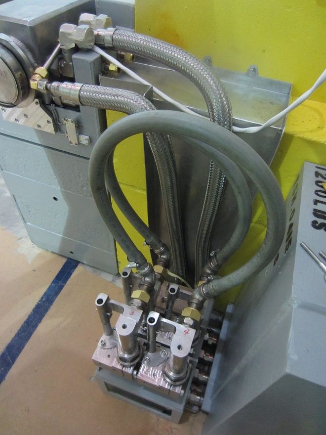
Isaac Earle | 100KW Beam Dump | Development | Upper Pb Shield and Water Hoses Installed |
The upper lead shield was installed this morning. Also the water hoses for lower lead shield, beam dump, and upper lead shield were all installed. See attached photos and hose installation information PDF. |
| Attachment 1: BD_Hose_Install_Notes.pdf
|


|
| Attachment 2: IMG_4407.JPG
|

|
| Attachment 3: IMG_4408.JPG
|

|
| Attachment 4: IMG_4410.JPG
|

|
|
8
|
Friday, December 05, 2014, 10:43 |
Isaac Earle | 100KW Beam Dump | Development | Lower Lead Shield Drain Line Installed |
A 1/8" SS tube was routed from the Swagelok fitting on the front of the lower lead shield to the service stand water catch tray as shown in the attached photos.
The tube was routed to fit in the cut-out and chamfered corner gaps of block TSH0387 in the de-rated EHDT shielding assembly TSH0293. |
| Attachment 1: IMG_4383.JPG
|

|
| Attachment 2: IMG_4384.JPG
|

|
| Attachment 3: IMG_4385.JPG
|

|
|
7
|
Wednesday, December 03, 2014, 10:45 |
Isaac Earle | 100KW Beam Dump | Development | BD Signals Traced from Service Stand to Junction Box |
On Dec 2 the cables from the BD service stand area to the junction box were traced to establish which sensors correspond to which cable number in the junction box.
The beam dump thermocouple probe cable numbers are as follows (as labeled on the beam dump and the TC block upper half):
TC#1: T44, TC#2: T55, TC#3: T11, TC#4: T22, TC#5: T66, TC#6: T77
The service stand water sensor cable numbers are as follows:
Inside Tray, East Side: 44
Inside Tray, West Side: 22
Under Tray, East Side: 33
Under Tray, West Side: 11 |
|
6
|
Wednesday, December 03, 2014, 10:36 |
Isaac Earle | 100KW Beam Dump | Development | Upper half of BD water blocks installed; Bypass loops installed |
On December 2 the upper half of the RH water blocks were installed (4 total) using a 0.030" thick 6061-T6 Al shim torqued to 60ft*lbs as was tested in Document-114260.
Bypass loops for testing the cooling system piping were installed as shown in the attached photo.
|
|
5
|
Wednesday, December 03, 2014, 10:16 |
Isaac Earle | 100KW Beam Dump | Development | Installation of Lower Lead Block and Beam Dump Insert |
On November 28th the lower lead shield was installed with 3/8" shimming at the front end, and 11/32" shimming at the rear end. The south and east faces were aligned as flush as possible with the lower center block. The beam dump insert was then placed on the rails in the lower lead shield.
Laser tracker measurements were performed by Michael Vogel, and he reported that the beam dump was 1.7mm high at the rear, and 0.8mm high at the front.
The lower lead shield was lifted, and 1/32" shimming was removed from the front, and 3/32" from the rear. The block was then placed precisely using the laser tracker with targets on the beam dump insert.
After placing the lower lead shield, Michael aligned the beam dump by shimming and adjusting the rail track, and was able to get all fiducial points within 0.2mm of the nominal position. |
|
4
|
Wednesday, November 26, 2014, 17:50 |
Isaac Earle | 100KW Beam Dump | Development | Installation of Lower Center Block (TSH0461) |
Painting and relabeling of the modified lower center block (TSH0461) was completed on Monday Nov 24. The height of the modified block was measured at the four corners using a tape measure and found to be approximately 533mm at all corners.
The block was lowered to the E-Hall and aligned on Tuesday Nov 25. No cantilever lift was required because the catwalk above the hatch had been removed. During the block installation one of the crane cables was contacting the concrete on the edge of hatch opening. Future installations should use a long sling or cable to prevent this. Photos of the installation are attached. Beamlines Group assisted with alignment using their laser tracker. Vertical alignment was achieved using 3x3" metal shims of various thicknesses placed at 4 corners of the block. North-south, east-west alignment was achieved by installing based on marks drawn on the E-Hall floor by Beamlines group. After initial placement, measurements were taken with the laser tracker, and the position was adjusted. The nominal positions of the beam dump according to installation drawing TSH0372 are:
East Face: x=-5926.3mm from EHBT CoP
South Face: y=2223.6mm from EHBT CoP
Top Face: z=-208.0mm from EHBT CoP
The laser tracker measurements of block position after final placement are as follows:
East Face: x = -5926.2 ~ -5926.9mm
South Face: y = 2220.9 ~ 2224.7mm
Top Face: z = -209.6 ~ 211.6mm
The East face is within 0.6mm of nominal position which is excellent (note that the east-west direction cannot be corrected using the alignment rail track). The south face position is within 2.7mm. This is fine because adjustment can be made to the north-south position of the rail track. The top face of the block is a maximum of 3.6mm below the nominal position which is also fine, as the lower lead shield block can be shimmed up to it's nominal position. Data from Beamlines Group is attached (note that 19.05mm must be added to each measurement to account for the distance from target base to center). The location of the measurement points on the top face are as follows.
North Side
--------------------------------------------
| 6 4 2 |
| |
| 5 3 1 |
--------------------------------------------
We will aim to have the bottom of the lower lead shield at z = -204.8mm (this leaves nominal 2mm space to be shimmed under the rail track to bring the BD flange center to beam height). Therefore the following thickness shims should be placed on the top of the lower center block.
Position 1: 5.8mm (suggest 1/8 + 1/16 + 1/32" shim = 5.6mm)
Position 2: 5.9mm (suggest 1/8 + 1/16 + 1/32" shim = 5.6mm)
Position 3: 6.8mm
Position 4: 6.0mm
Position 5: 5.1mm (suggest 1/8 + 1/16" shim = 4.8mm)
Position 6: 4.8mm (suggest 1/8 + 1/16" shim = 4.8mm)
Position 3 and 4 do not need shims, as the outer four corners should be adequate. |
| Attachment 1: Beam_Dump_Lower_Center_Block_Alignment_-_Nov_25_2014_(from_Darren_Blom).txt
|
south face
	       X	        Y	        Z
1	2205.2026	5957.3323	-303.2810

2	2205.6678	5958.5229	-538.5356

3	2203.4544	6661.3894	-290.0266

4	2203.9498	6689.3282	-525.2800

5	2201.8569	7334.6527	-292.9990

6	2202.5887	7360.9978	-547.9410


east face
	        X	        Y	        Z
1	2244.4638	5907.1393	-392.0822

2	2415.6983	5907.4958	-374.6703

3	2582.7607	5907.8437	-378.7617


top
 	        X	        Y	        Z
1	2248.4401	5960.5064	-191.5043

2	2587.3149	5952.5831	-191.6397

3	2259.9793	6731.8832	-192.5399

4	2561.7468	6719.6038	-191.7711

5	2259.9131	7157.1300	-190.8176

6	2558.7737	7188.2135	-190.5219
|
| Attachment 2: IMG_1110.JPG
|

|
| Attachment 3: IMG_1125.JPG
|

|
| Attachment 4: IMG_4297.JPG
|

|
| Attachment 5: IMG_4303.JPG
|

|
|
3
|
Friday, November 21, 2014, 13:37 |
Isaac Earle | 100KW Beam Dump | Development | Destructive Testing of 1" MDC Ceramic Breaks |
Testing was performed on the ceramic water breaks to be used on the beam dump water hose assemblies. The ceramic breaks are a custom MDC product with the following description: 3kV ceramic break, 1" OD tube 0.083" wall thickness, 2" length, 304SS tube stub each end, 250psi water rating (see TRIUMF PO# TR199315).
A load was applied perpendicular to the part, 12" away from the center of the ceramic, and increased incrementally until failure. Two parts were tested, which failed at 125lbf and 170lbf. Equivalent to 125ft*lb and 170ft*lb when converted to torque. Test data, photos of the failed specimens, and a more detailed description of the test setup are attached.
The purpose of the tests was to gain an understanding of how fragile the ceramic parts are. The results show that the ceramic breaks should be able to withstand the expected loads caused by the flexible hoses being pulled as the RH water blocks are installed or removed remotely using pole tools, however this operation should still be done cautiously. The ceramic breaks are at risk of failure if a torque of over 100ft*lb is applied, such as if someone were to stand on the ceramic breaks or the attached hose.
|
| Attachment 1: Ceramic_Water_Break_Test_#1.docx
|
| Attachment 2: Ceramic_Water_Break_Test_#2.docx
|
| Attachment 3: Test_#1_Broken_Sample.JPG
|

|
| Attachment 4: Test_#2_Broken_Sample.JPG
|

|
|
2
|
Wednesday, November 19, 2014, 13:49 |
Isaac Earle | 100KW Beam Dump | Development | Decision on Modifications to Lower Center Block (TSH0225) |
I received a call today from Jim Adamson at Kaltech regarding modifications to shielding block TSH0225.
They had finished removing 19mm from the bottom of the block, as well as removing 10mm of material from the side plates (TSH0246). He was wondering whether it was also necessary to remove material from the back plate (TSH0253) and weld the back plate to the 6" plate (TSH0252). I instructed him that it is not necessary to machine and weld the back plate. This decision is based on weld strength calculations I performed last week which showed that the existing welds are much stronger than what is required to take the load applied when lifting the block (FOS >> 10) |
|
1
|
Tuesday, November 04, 2014, 16:58 |
John Wong | 100KW Beam Dump | Maintenance | Testing Elog |
Tuesday, November 04, 2014, 16:58
This is a test.
|