| ID |
Date |
Author |
Category |
Type |
Module |
Target/Number |
Subject |
|
345
|
Wednesday, May 15, 2013, 10:20 |
Bevan Moss | Conditioning Station | Repair | | | Roof top chiller failed |
I have been getting a fault on the roof top chiller for the 2 tandem 7.5 ton chillers. I have checked and we have water flow and the temperatures are nowhere near freezing. I believe they are over heating as the fans on that side are not coming on. The blades are free to turn by hand but the VFD controller keeps saying off. I have tried turning it on and off and that also did nothing. I have contacted ESC for further advice. |
|
1511
|
Thursday, April 27, 2017, 16:58 |
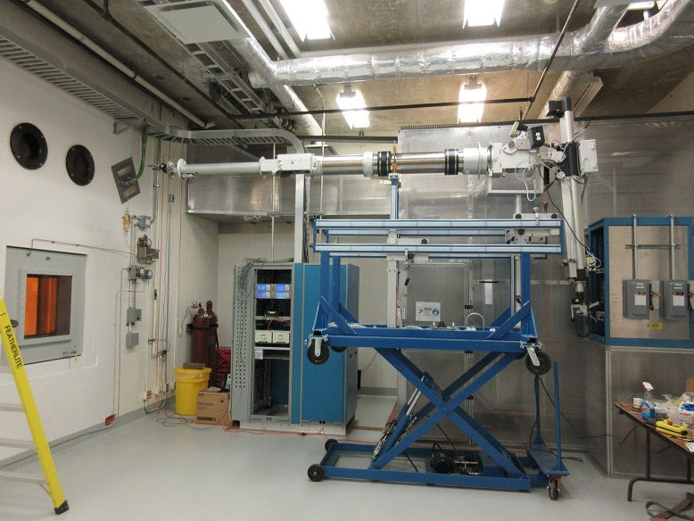
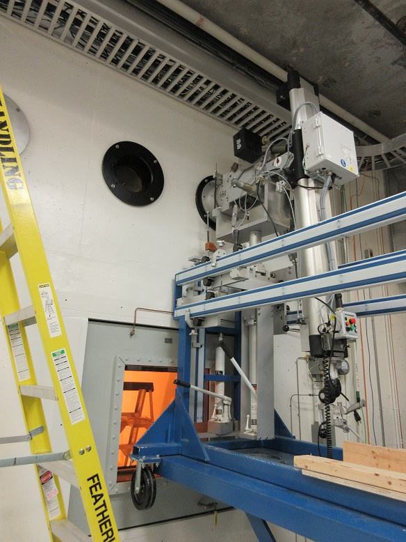
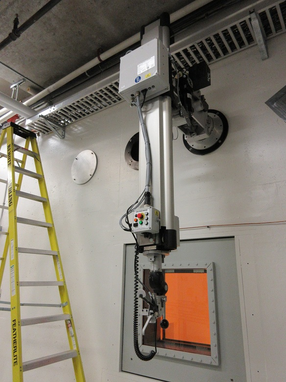
Isaac Earle | North Hot-Cell | Development | | | Right side NHC manipulator installed |
Installation of the NHC right side manipulator was completed yesterday. The three piece manipulator was assembled in the module assembly area on the manipulator cart which was then craned through the hatch to the NHC service area (the slave end had to be removed for it to fit through the hatch). The installation went relatively smoothly except for the second (cold side) piece of lead shielding around the thru tube which would not fit because the OD of the two halves were not concentric when assembled (arrived this way from CRL). The shielding was removed and 0.070" was cut down on the lathe, after which installation could be completed. The slave end lift bail and the pulley cover panel had to be removed for the manipulator to fit through the thru-tube. Both these items were reinstalled after the manipulator was in the wall, and it was confirmed that the slave end lift bail aligns with the slave-end removal hatch in the NHC roof. There was some difficulty getting the slave end to the horizontal position using the Y motion drive, also while preparing the manipulator for installation we noticed one of the Z motion tapes on the master side was sliding to the edge of one of the pulleys and rubbing - both these issues will be investigated at a later date.
We confirmed that it is possible to remove the master end using the manipulator cart. We will practice doing this at some point before the cell is commissioned. We will also do a run-through of slave end removal through the NHC roof.
Electronic copies of the Model-N installation and removal manual as well as the manipulator cart user manual are attached for future reference.
|
| Attachment 4: CRLD-1046-B_rev_1_Installation_Removal_Manual_(July_2013).pdf
|
-0.png "CRLD-1046-B_rev_1_Installation_Removal_Manual_(July_2013).pdf")
-1.png "CRLD-1046-B_rev_1_Installation_Removal_Manual_(July_2013).pdf")
-2.png "CRLD-1046-B_rev_1_Installation_Removal_Manual_(July_2013).pdf")
-3.png "CRLD-1046-B_rev_1_Installation_Removal_Manual_(July_2013).pdf")
-4.png "CRLD-1046-B_rev_1_Installation_Removal_Manual_(July_2013).pdf")
-5.png "CRLD-1046-B_rev_1_Installation_Removal_Manual_(July_2013).pdf")
-6.png "CRLD-1046-B_rev_1_Installation_Removal_Manual_(July_2013).pdf")
-7.png "CRLD-1046-B_rev_1_Installation_Removal_Manual_(July_2013).pdf")
|
| Attachment 5: Manipulator_Cart_User_Manual__(CRLD-1003).pdf
|
-0.png "Manipulator_Cart_User_Manual__(CRLD-1003).pdf")
-1.png "Manipulator_Cart_User_Manual__(CRLD-1003).pdf")
-2.png "Manipulator_Cart_User_Manual__(CRLD-1003).pdf")
-3.png "Manipulator_Cart_User_Manual__(CRLD-1003).pdf")
-4.png "Manipulator_Cart_User_Manual__(CRLD-1003).pdf")
-5.png "Manipulator_Cart_User_Manual__(CRLD-1003).pdf")
-6.png "Manipulator_Cart_User_Manual__(CRLD-1003).pdf")
-7.png "Manipulator_Cart_User_Manual__(CRLD-1003).pdf")
|
|
462
|
Tuesday, September 24, 2013, 14:46 |
Bevan Moss | South Hot-Cell | Repair | | | Right manipulator repair |
The right manipulator A-9885 Handle Cable Assembly has been repaired by Maico and myself. We repaired the manipulator following some verbal instructions from Chad on the modified repair strategy. This allows the repair to be completed without going into the hot cell. The instructions in the repair manual are very vague and can actually cause problems. For example it is best to pin the manipulator before completing any work. Other than that the work went smoothly with the exception that the counter weight hangs up on the manipulator occasionally and can cause the cable to come off of the pulley. Also it appears that the left manipulator has had the cable installed incorrectly as it rides on the housing of the wrist. |
|
486
|
Wednesday, October 02, 2013, 13:44 |
Bevan Moss | South Hot-Cell | Standard Operation | TM4 | | Right Coil is leaking |
Today Maico and Travis completed and electrical test to determine the right and left coil on TM4. The left coil is the negative side. From there Maico pumped on both lines for a leak test. The leak cart pumped down to its lower limits on the left line and there was no response when sprayed with helium. The right line would not pump below 2.5 x 10^-2 Torr and had a base leak rate of 3.3 x 10^-7 atm*cc/sec (this indicates a massive leak). Without spraying helium the leak cart responded and peaked at 1.9 x 10^-6 atm*cc/sec. Attached is a picture of the module indicating the line.
|
| Attachment 1: tm4leak.jpg
|

|
|
2512
|
Thursday, December 21, 2023, 09:37 |
Ferran Boix Pamies | ITE | Development | | | Rewiring of TC multiping wires |
| Thursday, December 21, 2023, 09:36. ITE multipin wires 12-13-14-15 were rewired from the RF driver box to a TC datalogger inside the HV cage. A webcam was also installed to monitor the TC values during operation. This is only a temporary setup to be upgraded during shutdown. |
|
1962
|
Wednesday, August 14, 2019, 11:43 |
Travis Cave | South Hot-Cell | Standard Operation | TM2 | Ta#58 and no target. | Results of electrical checks post beam at the south hot cell. |
Here are the results of the electrical done at the south hot cell post beam of with the Ta#58 target attached and with just the module no target attached. |
| Attachment 1: TM2_elec_chk_Ta58_post_beam_shc.pdf
|

|
| Attachment 2: TM2_Elec_chk_no_tgt_shc_Aug-14-2019.pdf
|

|
|
1681
|
Monday, January 22, 2018, 07:47 |
David Wang | Conditioning Station | Standard Operation | TM3 | | Restarted TM3 vacuum sysytem after site power bump |
All TCS and TM3 vacuum pumps are started successfully. |
|
1858
|
Monday, January 14, 2019, 07:07 |
David Wang | Conditioning Station | Maintenance | TM2 | | Restarted TCS vacuum system . |
No issue. |
|
2093
|
Wednesday, May 20, 2020, 13:19 |
David Wang | ITE | Maintenance | | | Restart of ITE turbo pumps. |
PLC6 drop out in weekend caused the ITH MP1 and MP1s stopped. ITE turbo pumps were running still after that. Without back up pump, TPs started to trip off later . I found TP1,TP3, and TP4 were tripped off this morning. And , The rest pumps ran with high current draw. Jon Aoki restarted back up pumps and ITE turbo pumps. The ITE vacuum system works fine now. |
|
614
|
Thursday, March 06, 2014, 12:59 |
David Wang | Conditioning Station | Maintenance | TM1 | | Restart TM1 and CS TPs |
Restarted TM1 and CS turbo pumps after the power off. Everything is fine . |
|
1843
|
Wednesday, January 02, 2019, 10:26 |
Anders Mjos | Conditioning Station | Standard Operation | | | Restarrted TP1S |
Found pumps off after the holidays. Restarted roughing pump and TP1S |
|
846
|
Tuesday, February 17, 2015, 13:07 |
Anders Mjos | ITW | Development | | | Resistance measured of TGHT and TBHT lines to ITW |
See e-log entry for ITE for details. The copper bars have not been removed. They can be used for testing the new power supplies.
Local measurement was done by Ray with a voltmeter. The voltmeter was consistent with EPICS readback and local readback on the power supplies. A voltage drop of 0.137 V @ 580 A was measured across the bus bar from the TGHT power supply to the cooled transmission lines. |
|
903
|
Tuesday, April 28, 2015, 11:09 |
Anders Mjos | ITW | Maintenance | | | Resistance measured of TGHT and TBHT lines to ITW |
The new TBHT and TGHT power supplies were brough up to high current; 350 A and 420 A respectively. The TGHT power supply was limited by PLC to 420 A. The resistance calculated for both the TBHT and TGHT copper lines from the electrical services room to the ITW pit was 1.35 mOhm. See attached spreadsheet for details.
Dave Morris has been contacted to correct the current limit for the TGHT supply to 600 A. |
| Attachment 1: Resistance_from_Electrical_Room_to_Target_Station.xlsx
|
|
845
|
Tuesday, February 17, 2015, 13:06 |
Anders Mjos | ITE | Development | | | Resistance measured of TGHT and TBHT lines to ITE |
The copper bars was installed by David and Anders. After the measurements were completed, the copper bars were removed.
See photo and attached spread sheet. |
| Attachment 1: 002.JPG
|

|
| Attachment 2: Resistance_from_Electrical_Room_to_Target_Station.xlsx
|
|
2609
|
Thursday, June 13, 2024, 11:44 |
David Wang | Conditioning Station | Repair | TM2 | | Replaced several o ring seals on TM2 service cap. |
couple of E-8 to low E-7 atm.cc/sec leak were found on TM2 service cap top air to vacuum o rings. Replaced these leak o ring seals including o ring on IG1 and steerer service panel,o rings on MSP, EE, D blue nylon and copper feed through, and o ring on a round blank off beside MSP terminal on second row.
2024-july-03 update: TM2 was leak checked again at TCS. no air to vacuum leak on module top. i helium pressure tested(60psi) all water cooling lines (except HS) . They are leak free. |
|
992
|
Friday, July 10, 2015, 14:41 |
Anders Mjos | Conditioning Station | Maintenance | TM1 | | Replaced roughing pump |
The roughing pump was replaced with a more leak tight pump due to the discovery of Rn-220 migration while roughing on TM1 in TCS |
|
1687
|
Wednesday, February 14, 2018, 10:06 |
Anders Mjos | ITW | Maintenance | TM2 | | Replaced parker couplings on Window cooling line |
By Anders & David. Couplings will be taken apart for inspection. |
|
2311
|
Wednesday, March 02, 2022, 10:51 |
David Wang | ITE/ITW | Standard Operation | | | Replaced old turbopump and 2A3M20 wire scanner are transferred to cyclotron tunnel. |
Replaced 9 old turbo pumps from ITE/ ITW and one 2A3M20 wire scanner from ITE are transferred to cyclotron tunnel for storage. It is TH RAD waste cleanup task in winter shut down. |
|
164
|
Thursday, August 23, 2012, 07:34 |
David Wang | ITW | Repair | | | Replaced broken air lines on ITW HARP5B cylinder. |
Prob guys replaced broken air lines on ITW HARP 5B Cylinder.Several shielding blocks had been moved out to make the cylinder accessible. After the replacement,the HARP5B works fine.All shield blocks had been moved back to original position. The job is done. |
|
2613
|
Friday, June 14, 2024, 16:04 |
Carla Babcock | ITW | Repair | TM4 | UC#45 | Replaced and reinstalled electronics in ITW cage |
ITW has been behaving badly at higher voltages recently, even without protons on. I conditioned it up to 50kV with heaters off in the TCS and it was fine. But when I tried to do the same with heaters on in the station, it was quite sparky and it kept tripping the TGHT/TBHT. I went to 49kV where it was unstable, then lowered to 48kV where it looked fine for 30mins. But even operating at 40kV, it tripped the heaters several times. The TBHT voltage came back lower than before on the last trip, so I am getting worried about it.
I decided to make sure all the electronic spark protection was ok in the faraday cage. There is a resistor/gmov combination across the terminals of each TGHT/TBHT in which Tomislav replaced the gmovs for me because his tester did not work at those low voltages, so we couldnt see if they were broken. The electronics diagram called for 18V gmovs, the replacements are 22V because that's all we have.
We also tested and re-installed the capacitor-gdt-resistor combinations that John installed last year from TGHT/TBHT bubars to HV common. I originally removed them because we couldn't bias a FEBIAD with them on - this still has to be investigated. The measured values are 0.148uF, 90kOhms and a breakdown voltage on the gdt of 410-450V.
Hopefully this prevents sparking the power supplies off.
Sunday, June 16, 2024, 07:03 : power supplies have not tripped off since electronics repair. See data/TM4sparkingbehaviour_June152024.dat for sparking frequency over ~10hrs of protons (5-14uA). >14 sparks during this time (14 captured by PLC when voltage dropped, many more current peaks). |