| ID |
Date |
Author |
Category |
Type |
Module |
Target/Number |
Subject |
|
893
|
Tuesday, April 21, 2015, 13:01 |
Grant Minor | ITW | Development | TM2 | | TM2 MK4 Optics Tray - banana plug bore modification (on bench) |
The MK4 optics tray prepared for TM2 (as per ITA6082) had an undersized bore for the banana plug, making insertion of the plug extremely difficult / impossible.
Reference stores parts were collected to check the fit: male plug 3-4/01152 and female jack 1-6/1201. The size of the female jack was checked with a #21 drill at .159".
The bore on the optics tray was drilled out dry using the #21 drill to the same depth as the original blind hole, by Maico and Dan McDonald. Chips were carefully collected in a rag, and the hole was blown out with compressed air.
The fit was checked to be snug but possible, using the male plug and the Remote Handling ultem base (ref ITA6023).
Redlines and photos are attached.
|
| Attachment 1: ita6092_redlines_gminor_21apr2015.pdf
|

|
| Attachment 2: TM2_Optics_Tray_Bore_Mod_21Apr2015_1.JPG
|

|
| Attachment 3: TM2_Optics_Tray_Bore_Mod_21Apr2015_2.JPG
|

|
| Attachment 4: TM2_Optics_Tray_Bore_Mod_21Apr2015_3.JPG
|

|
|
899
|
Monday, April 27, 2015, 16:12 |
Keith C Ng | South Hot-Cell | Development | TM2 | | Ceramic Standoffs in TM2 source tray steerer assembly |
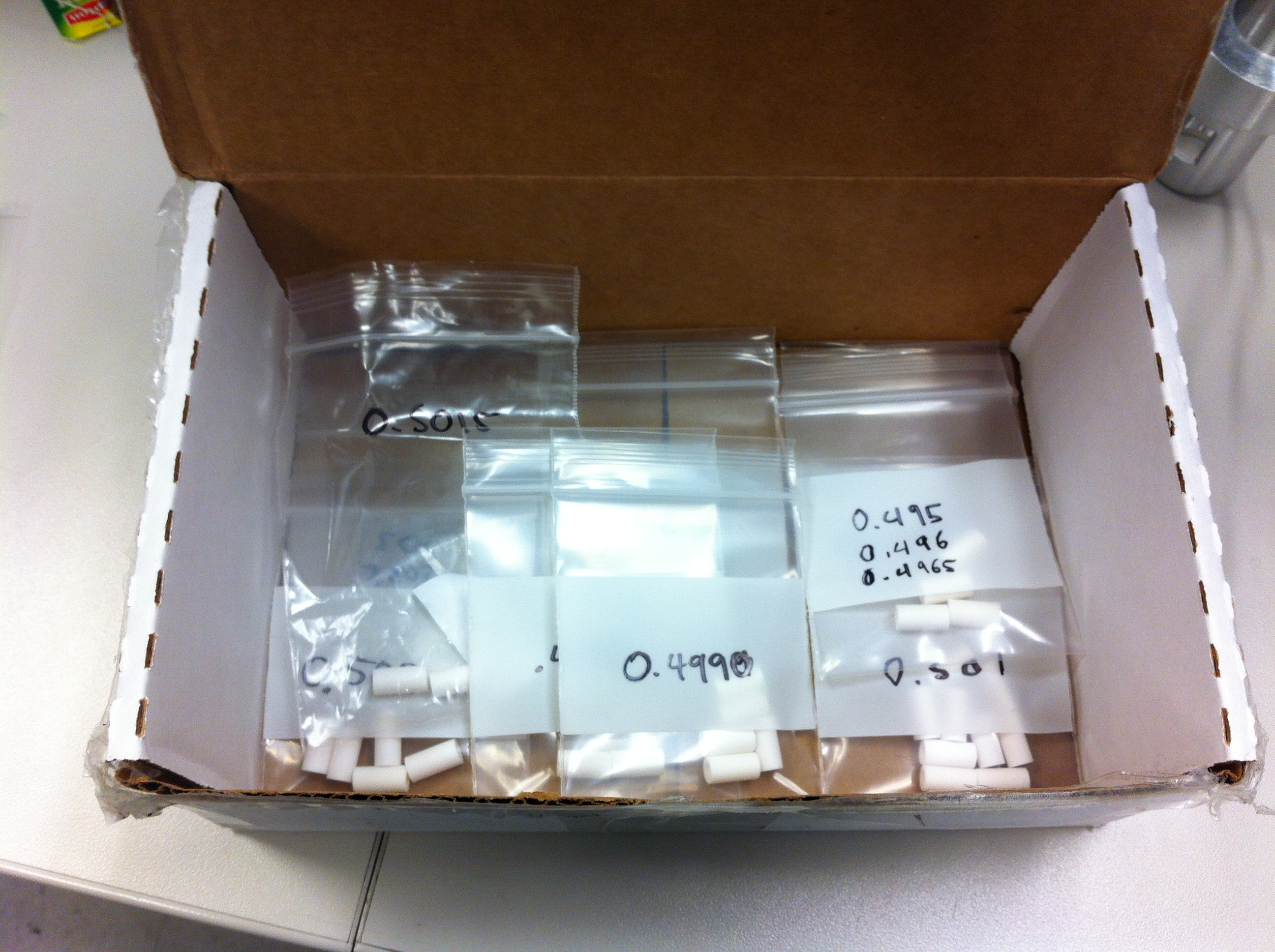
On drawing ITA6008 for the Encole 0.5" ceramic standoffs there is a note to match pairs of ceramics to within +/-0.001". This step was missed on the current build of TM2 source tray (ceramics were not measured).
Measured the lengths of the rest of the ceramic standoffs in inventory and they range from 0.5035" to 0.4950" in length. The ceramics have been sorted by length and grouped into bags.
 |
|
900
|
Monday, April 27, 2015, 17:09 |
Grant Minor | ITE | Development | TM2 | | TM2 - New Source Tray - Water Block Seal Groove Inspection Report |
The water blocks soldered to the TM2 cooling lines (see Ref. Assy. ITA6144) were inspected.
See attached inspection reports and drawings.
It was found that only 18% of the seal groove diameters and 55% of the depths were in spec.
The source tray must be tested on the test stand with c-seals to ensure that these blocks will seal properly on the module. |
| Attachment 1: IMG_1859.JPG
|

|
| Attachment 2: TM2_New_Source_Tray_Water_Block_Inspection_Results_24_April_2015.pdf
|

|
| Attachment 3: TM2_water_block_inspect_24Apr2015.pdf
|


|
| Attachment 4: TM2_New_Source_Tray_Water_Block_Inspection_Results_April_2015.xlsx
|
|
906
|
Thursday, April 30, 2015, 08:50 |
Travis Cave | South Hot-Cell | Standard Operation | TM2 | No target | Module move |
TM#2 with no source tray has been moved from the north east silo to the south hot cell. |
|
907
|
Friday, May 01, 2015, 08:27 |
chad fisher | South Hot-Cell | Repair | TM2 | | Containment Box Removal |
Containment box has been removed in preparation for wire replacement. |
|
908
|
Friday, May 01, 2015, 13:48 |
David Wang | South Hot-Cell | Standard Operation | TM2 | | Target Hall Scheduled Activities April 07 - June 26 2015 update |
Target Hall Scheduled Activities April 07 - June 26 2015 update. 2015-05-01. All TH scheduled jobs are finished on time this week. |
| Attachment 1: Target_Hall_Scheduled_Activities__Apr_07_to_June_26_2015.mpp
|
| Attachment 2: Target_Hall_Scheduled_Activities__Apr_07_to_June_26_2015.pdf
|


|
|
910
|
Tuesday, May 05, 2015, 10:57 |
chad fisher | South Hot-Cell | Repair | TM2 | | TM2 Wiring |
Old wiring was removed yesterday, new wiring run thru the vacuum chase. Old IMG gauge removed today, new cable trays installed and wires installed into cable trays. |
| Attachment 1: TM2_New_Wiring_20150504_13.jpg
|

|
| Attachment 2: TM2_Wiring_20150505_10.jpg
|

|
|
911
|
Wednesday, May 06, 2015, 14:30 |
Travis Cave | South Hot-Cell | Repair | TM2 | No target | Wiring of TM#2 |
Wires for TM#2 steering elements, and png gauge have been run down to the containment box level. Chad has placed them in the little cable trays. Slack has been pulled back. and termination of the wire will be done on the 7th of May. A modification was done to the signal line of the png gauge wire ultem block, as grounded screw was inserted to allow for strain relief so the end would hopefully quit breaking. See attached pictures for the details. |
| Attachment 1: Photo_2015-05-06_8_26_10_AM.JPG
|

|
| Attachment 2: Photo_2015-05-06_8_26_17_AM.JPG
|

|
|
912
|
Thursday, May 07, 2015, 11:02 |
Travis Cave | South Hot-Cell | Repair | TM2 | No target | Wiring of TM#2 |
Wires in TM#2 have been terminated at the top of the module. |
|
914
|
Monday, May 11, 2015, 11:20 |
David Wang | South Hot-Cell | Standard Operation | TM2 | | Target Hall Scheduled Activities April 07 - June 26 2015 |
The schedule has some changes due to new TM2 source tray coil cooling line leaking at test stand. Now,It is re-scheduled in such an estimation that TM2 source tray could be ready at teat stand by this Friday(May-15th). see attachment 1,2.
2015-05-12, Changed and updated the TH activity schedule according to Dons new beam schedule which is re-arranged after the coil line leaking issue. See attachments 3,4. No major conflicts has been found on the new schedule.
2015-05 25, Updated the TH activity schedule according to present TM2 job processing. See attachment 5,6. |
| Attachment 1: Target_Hall_Scheduled_Activities__Apr_07_to_June_26_2015.mpp
|
| Attachment 2: Target_Hall_Scheduled_Activities__Apr_07_to_June_26_2015.pdf
|


|
| Attachment 3: Target_Hall_Scheduled_Activities__Apr_07_to_June_26_2015.mpp
|
| Attachment 4: Target_Hall_Scheduled_Activities__Apr_07_to_June_26_2015.pdf
|


|
| Attachment 5: Target_Hall_Scheduled_Activities__Apr_07_to_June_26_2015.pdf
|


|
| Attachment 6: Target_Hall_Scheduled_Activities__Apr_07_to_June_26_2015.mpp
|
|
915
|
Wednesday, May 13, 2015, 13:55 |
chad fisher | South Hot-Cell | Repair | TM2 | | Shutter removal |
TM2 has been successfully de-shuttered.
All went pretty much according to plan except I had to remove one fastener out of the upper wiring harness (the one that has just been installed) to allow for enough clearance to rotated the shutter guide out of the way...I shutter to think what would have happened otherwise...anyways...
Close inspection of the shutter does show that the "thin" area isn't in very good shape; whether this is a result of removal or just the way it was is hard.Due to the ease of removal I would quess that it may have been a preexisting condition. That being said...I think we may want to consider replacing it.
|
| Attachment 1: TM2_20150513_131339.jpg
|

|
| Attachment 2: TM2_20150513_134232.jpg
|

|
|
917
|
Tuesday, May 26, 2015, 11:49 |
Grant Minor | Assembly/Bench Test | Repair | TM2 | | TM2 New Source Tray - Braze & Solder Report - 22 May 2015 |
Hello,
For reference, I have attached a list of all solder joints in the TM2 Source Tray, and the alloys used for the most recent build (as per ITA6144). I have also provided data sheets for the alloys, and PDF copies of all the drawings calling out the joints.
Certanium 34 C (222 deg C melt point) was used for all low-temperature solder applications, except for the steel inserts in the water blocks. Previous revisions of the Source Tray drawings called out a higher-temperature McMaster lead-based solder (304 deg C melt point). The change to Certanium 34 C on the prints was made in Bevan's era, during the transitional update of the source tray drawings between the TM1 and TM3 source tray projects, just before I took over updating the drawing packages. I believe Bevan made this change on general advice from Guy Stanford, who stated that Certanium 34 C is a much easier solder to work with and makes a more mechanically reliable joint. However, the change really should have had more review and validation testing before being implemented.
This said, we now have a source tray that uses Certanium 34 C, and rework of every joint would set us back too far in the schedule to meet the deadline, so we will have to run with it as it is.
Of particular concern are the joints on the target oven and coil heating blocks, which are now using a lower temperature solder (222 deg C melt vs 304 deg C melt). We have experienced a coil block failure on TM4 due to a failed solder joint, although the failure mode is not known for certain. We also had two recent failures on the test stand of a coil joint soldered with Certanium 34 C, but this was due to an error in the connection of cooling water to the joints (i.e. the joints had no coolant flow and the solder melted... this is expected!).
Anders and I have performed independent thermal analysis on the joints due to the radiative and electric heating from the target, and have concluded that even with a lower temperature solder, there is a lot of margin, so the risk seems to be low. This work will be published in a separate report to be circulated later.
Thank you and regards,
Grant |
| Attachment 1: TM2_Source_Tray_-_Braze_and_Solder_Report_File_-_22May2015.pdf
|


|
| Attachment 2: 1005_Bare_DS.pdf
|

|
| Attachment 3: 1005_Bare_MSDS.pdf
|


|
| Attachment 4: Certanium_34C_Data_Sheet.pdf
|


|
| Attachment 5: Certanium_34C_MSDS.pdf
|


|
| Attachment 6: mcmaster_carr_solder_7667A23.pdf
|

|
|
918
|
Tuesday, May 26, 2015, 14:34 |
chad fisher | South Hot-Cell | Repair | TM2 | | Shutter replacement |
The shutter in TM2 was successfully replaced today.
New lock washer and nut were installed onto shutter and nut torqued to 120 ft lbs.
Shutter guide alignment tool was used to insure tapped shutter guide holes were concentric with thru holes in shutter side mounting panel, button head screws replaced and torqued to 110 ft-lbs.
The shutter was manually cycled open and closed by David and everything is to operate well. |
| Attachment 1: Shutter.jpg
|

|
|
919
|
Wednesday, May 27, 2015, 08:57 |
Travis Cave | Conditioning Station | Standard Operation | TM2 | | Module moved |
TM#2 with no source tray has been moved from the south hot cell to the conditioning station. |
|
920
|
Friday, May 29, 2015, 09:16 |
Travis Cave | Conditioning Station | Standard Operation | TM2 | no target | Module moved |
TM#2 with no source tray has been moved from the conditioning station to the north east silo. |
|
933
|
Thursday, June 04, 2015, 07:44 |
Dan McDonald | Assembly/Bench Test | Development | TM2 | | Movement of TM2 source tray to alignment area in ISAC |
Once the test stand was vented and all lines purged Anders Mjos and myself jigged up the water blocks and proceeded to remove the TM4 SiC#31 target used during the testing, Einso lens and steerer. Once these components where removed we transferred the source tray to the transport plate and moved it to the alignment area. |
|
934
|
Thursday, June 04, 2015, 08:27 |
chad fisher | Assembly/Bench Test | Repair | TM2 | | TM2 Source Tray C-seal removal and inspection |
Source tray for TM2 has been moved to the alignment area by Dan and co.
This morning Dan removed the c-seals used during the test and he and I inspected the sealing surfaces to determine if they need to be cleaned...they do..trace indium was present on all blocks.
Surfaces will be cleaned before final alignment check.
|
| Attachment 1: TM2_20150604_01.jpg
|

|
| Attachment 2: TM2_20150604_02.jpg
|

|
| Attachment 3: TM2_20150604_03.jpg
|

|
| Attachment 4: TM2_20150604_04.jpg
|

|
| Attachment 5: TM2_20150604_05.jpg
|

|
|
935
|
Monday, June 08, 2015, 14:40 |
chad fisher | Assembly/Bench Test | Repair | TM2 | | TM2 Source Tray Final Alignment Check |
Final Alignment checks of the TM2 source tray took place today.
Mater Jig: Front - 0,0 Back - 0 left, right, .005 low
Tray: Front .001 High, .001 right Back - .001 right, .008 low
Which equals Tray: front .001 high, .001 right back: .001 right, .003 low in comparison to the master jig which is both within spec and within reason to pre-soldering numbers.
Steerer was out significantly and currently sits at .003 high, .002 right wrt. master jig.
More refinement on the steerer tomorrow and check on the optics tray as well. |
|
936
|
Tuesday, June 09, 2015, 09:49 |
chad fisher | Assembly/Bench Test | Repair | TM2 | | TM2 Source Tray Final Alignment Check |
Final alignment continued this morning.
Steerers have been aligned to 0.001 low, 0.000 left/right wrt master jig.
Optics tray required some adjustment as well and is now at:
Front 0.000 left/right, .001 high wrt master jig
Back 0.001 high, 0.000 left/right wrt master jig
Febiad coil conductor blocks have been reset with the master target jig as well...as they have been on and off during the test stand test.
A few components have been removed during the test stand test (such as feet required for tranfser jig) which I will now hunt down.
Otherwise i believe we are ready. |
|
937
|
Tuesday, June 09, 2015, 14:36 |
chad fisher | Assembly/Bench Test | Repair | TM2 | | TM2 Source Tray Final Inspection |
Final inspection took place with Pierre, Grant, Friedhelm and Anders present.
Two action items were raised:
1) check routing of 9 pin connector line
2) Check orientation of 9 pin water block
Chad pointed out concerns on clearances between a target and conductor block waterlines, possible optics tray alignment issues (that it had changed slightly from the initial alignment), and gap between steerer housing and ground electrode due to alignment. |
| Attachment 1: 20150609_132818.jpg
|

|
| Attachment 2: 20150609_132825.jpg
|

|
| Attachment 3: 20150609_132833.jpg
|

|
| Attachment 4: 20150609_132839.jpg
|

|
| Attachment 5: 20150609_132851.jpg
|

|