 Friday, June 12, 2015, 10:16, Isaac Earle, 100KW Beam Dump, Development, Beam Dump Vac Seal Vent & Test Friday, June 12, 2015, 10:16, Isaac Earle, 100KW Beam Dump, Development, Beam Dump Vac Seal Vent & Test
|
- Vacuum has been pumping steadily on the EHDT section since June 8, reaching 3.2E-8 Torr at 8am today (June 12)
- Leak check performed this morning by Anthony Ip: no leaks
- Vacuum vented and re-pumped, leak check repeated: no leaks
- Reached 5.0E-7 Torr by 9:20am
Installation of shielding over the beam dump will begin next Tuesday. |
Thursday, May 28, 2015, 16:08, Isaac Earle, 100KW Beam Dump, Development, Beam Dump Vac Seal RH Test & Installation 
|
The following work was performed on May 27 & 28, 2015:
- The beam dump 10kW Remote Handling setup was arranged as shown in the attached procedure
- The EHDT split ring clamp was found to be installed too far downstream and the pole tool could not be installed properly; the position was adjusted
- The cuff of the previously installed used seal was found to be damaged because it was not located properly on the EHDT side flange at the bottom when the clamp was closed. Thorough inspection (visual from top, camera for bottom) must be used in the future to prevent this from happening again
- Flange gap was measured with the beam dump in far upstream and downstream positions: .190" and .762"
- Seal width is 0.255", and cuff width is 0.475", giving 0.297" clearance for installation, and .065" bellows compression when closed
- EHDT beam pipe was adjusted approximately 0.125" downstream to give more bellows compression with seal installed and the BD advanced upstream
- New flange gaps: 0.083" and 0.649; New instillation clearance: 0.174"; New bellows compression: 0.172"
- Two trial seal installations were performed according to the attached procedure (no major issues encountered)
- A new helicoflex seal was used for the final installation (also according to the procedure). One of the clamp jaws did not seat properly around the flanges at beginning of travel; this was overcome by backing up 1/4 turn and adjusting the clamp angle to get the jaws seated properly. After this the clamp closed normally.
- A helium leak check was performed by Anothony Ip from Vacuum Group: No leaks found!
See attached procedure for full details and photographs (updated document uploaded June 2 to include comments from Ron K.) |
|
Monday, June 08, 2015, 15:23, Isaac Earle, 100KW Beam Dump, Development, Beam Dump Seal Re-Install
|
On Monday June 8 the following work was performed by Isaac Earle and Keith Ng:
- EHDT beamline vented
- Band clamp and o-ring seal removed
- Flanges cleaned with methanol and Kimwipe
- Flanges inspected visually: clean and scratch free
- New seal prepared as per TEL5568 from old 1997 batch of seals (as decided at Friday June 5 meeting)
- Seal cleaned with methanol and Kimwipe
- Seal installed remotely following procedure attached to Ariel E-Log #18 (install went smoothly, no catching of clamp jaws)
Rocking the clamp back and forth while tightening seemed to be a good technique to avoid jaws catching on outside of flanges
Clamp began getting stiff with around 5/8" of gap remaining to stop ring. It gradually got stiffer as travel progressed until reaching hardstop
- Inspected visulally close up: all appeared normal
- Vacuum pumped at 10:15am, Leak check performed around 11:30am - Leak tight
- Will leave the BD under vacuum for a few days, then attempt to vent, repump, and repeat leak check (which caused failure before)
- RH bridges removed to allow water lines in north-west corner to be reinstalled
|
|
Friday, December 19, 2014, 14:05, Isaac Earle, 100KW Beam Dump, Development, Beam Dump & Lead Shielding Design Documentation
|
As there likely won't be an opportunity to properly document the design of the beam dump insert and cooled lead shielding in design notes, a list of design reviews, released on Docushare is provided below. These provide a reasonable overview of the design process for each item. In addition the attached PDF of scanned notes provides detailed information on the lead shielding design. Further notes, ANSYS documents, meeting minutes, concept reviews, etc, can be be found on Isaac Earle's hard drive. Released drawings for each completed design are available on the PDM Works Vault.
DR-P0104-35 (Document-110856): Design Review for the e-Linac 100kW Tuning Dump Pb Shielding
DR.P0104-23 (Document-104081): E-Linac 100kW Tuning Dump Water Cooling Package Concept Design Review
DR-P0104-41: Design Review for the Tuning Dump Local Shielding (10kW De-Rated)
DR.P0104-24 (Document-104082): E-Linac 100kW Beam Dump Insert Design Review
DR.P0104-32 (Document-109104): E-Linac 100kW Beam Dump Shielding Design Review |
|
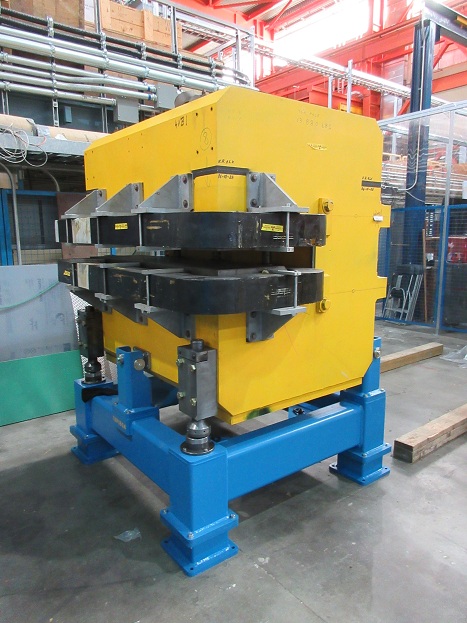
Tuesday, May 02, 2017, 16:52, Isaac Earle, BL4N, Development, BL4N 35-deg bender stand hardened parts tested
|
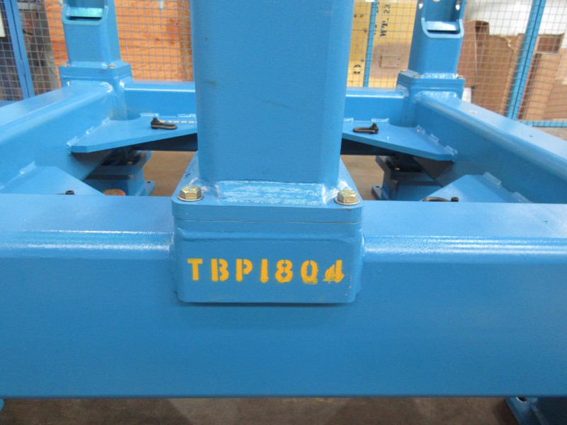
Hardness testing was performed on 1 sample each of parts TBP1822 and TBP1823 (part of the 35-deg magnet stand assembly TBP1804), They were found to be 60-60.5 Rc and 60-61 Rc respectively which is within spec. The alloy used to fabricate these parts was AISI #8620. The testing was performed by Precision Heat Treat in Surrey who also performed the heat treatment at an earlier date. |
|
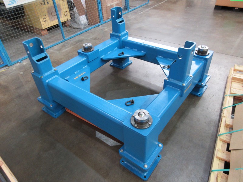
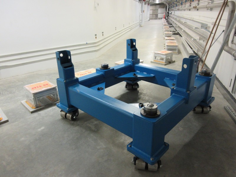
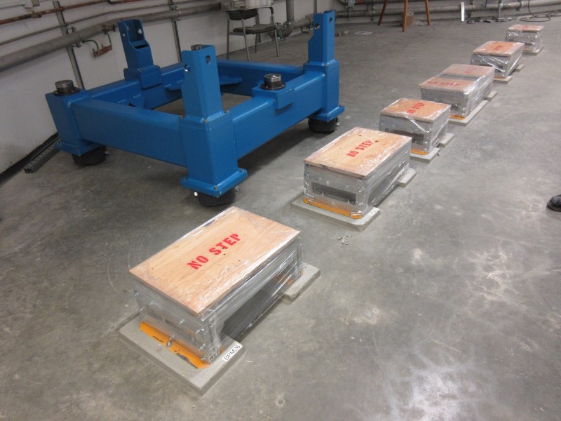
Monday, June 05, 2017, 16:16, Isaac Earle, BL4N, Development, BL4N 35-deg bender stand assembly complete 14x
|
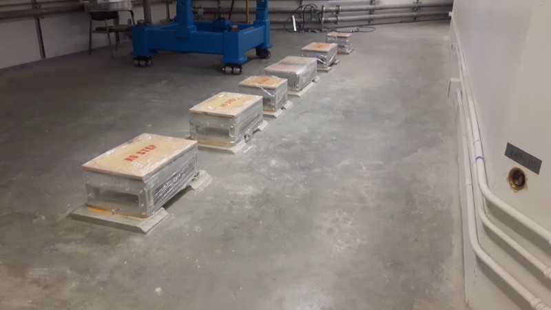
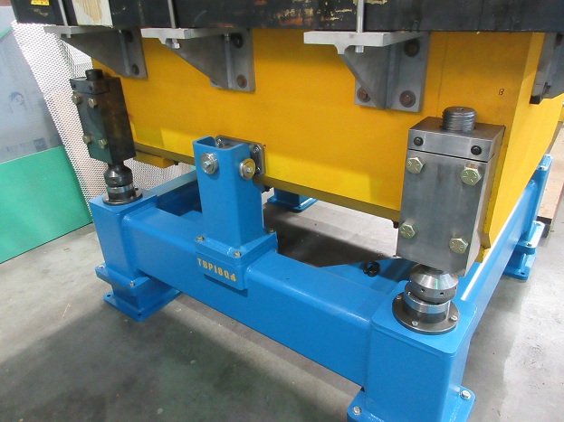
Assembly of two complete bender stands was completed on Friday June 2nd as well as installation of new hardware on the dipole magnets for support, adjustment, and seismic restraint. All parts were installed according to drawing TBP1804.
One of the frames was assembled with the caster wheel configuration. This frame was pushed from the proton hall B2 level to its final installation location in the ARIEL tunnel. The frame was a tight fit around the first corner around BPM 26 but it could still pass by without having to remove any items including the electrical boxes on the right side of the tunnel (when facing towards ARIEL). Part of the grouting for the BPM 26 support stand and the next three stands after that was ground away to allow more clearance for the frame. The nut/bolt on the frame casters on one side were swapped which also provides an additional ~1/8" clearance. After these modifications the stand was pushed out past this area and then back to its installation spot confirming that there is now ample clearance.
The other frame was assembled in the configuration with stand legs. This frame has been moved to the proton hall extension loading bay to be used for magnet field testing.
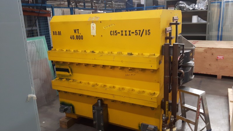
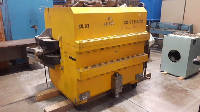
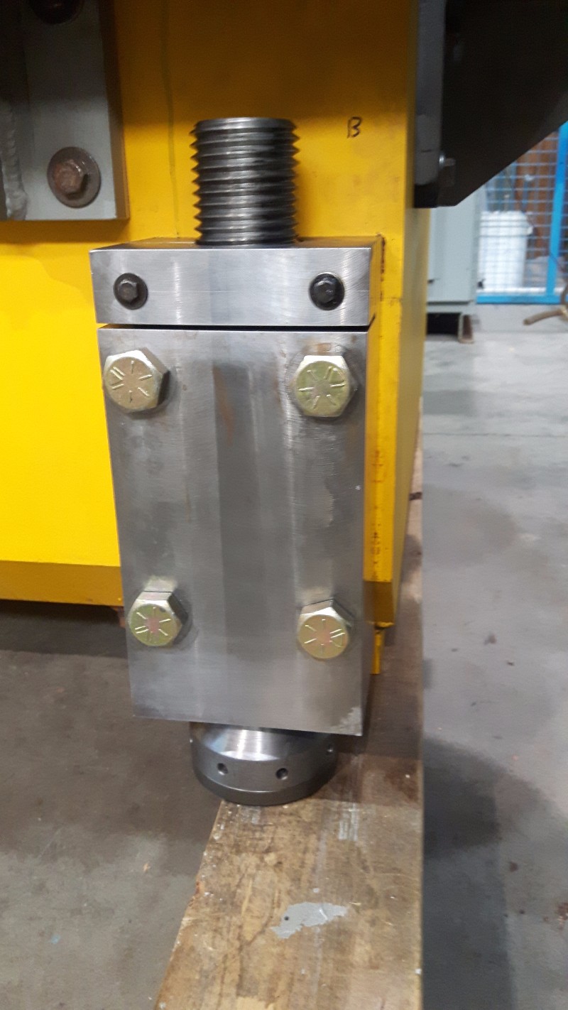
Both dipole magnets have been assembled with the new adjuster blocks and support legs. For the magnet labeled “No.01” the original support legs were removed, cleaned in the ultrasonic cleaner, and then reassembled with way oil The support leg support pads (TBP1822) were replaced with new parts, but all other parts were reused. For the other magnet, labeled “No.03”, new support legs were fabricated because it was supported differently in its previous location and did not have these parts. The fasteners attaching the adjuster blocks and support legs to the magnets were torqued to the recommended torque for each fastener based on the fastener grade and size.
Various minor changes to the design were made since the release of drawings, primarily to improve ease of manufacture. As-built drawings will be released after the magnets have been installed on the stands in case additional changes arise.
|
|
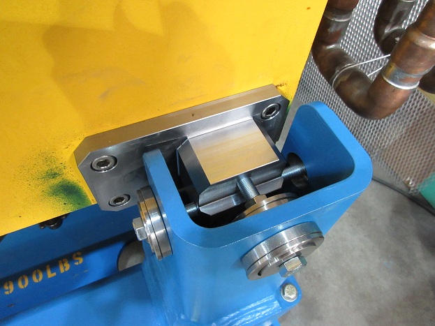
Thursday, June 01, 2017, 15:25, Isaac Earle, BL4N, Development, BL4N 35-deg bender adjustment blocks modified to fit magnet
|
Adjustment blocks were installed on the second dipole bender today (labeled "No. 03" "C15-III-57/15"). The mounting holes on the magnet were not aligned properly, so modification was required for two of the blocks. The counterbored holes on TBP1809 were slotted 0.10" vertically, and on TBP1808, 0.06" horizontal slotting was required. A stress analysis was performed to confirm that the blocks are still strong enough to withstand the seismic loads (PDF attached).
|
|
Wednesday, June 28, 2017, 17:37, Isaac Earle, BL4N, Development, BL4N 35-deg bender "No. 1" installed on magnet stand
|
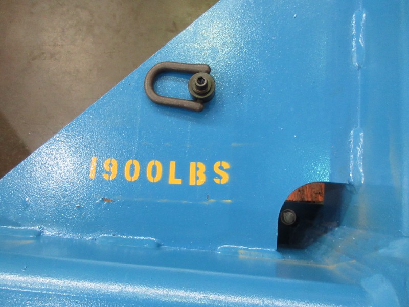
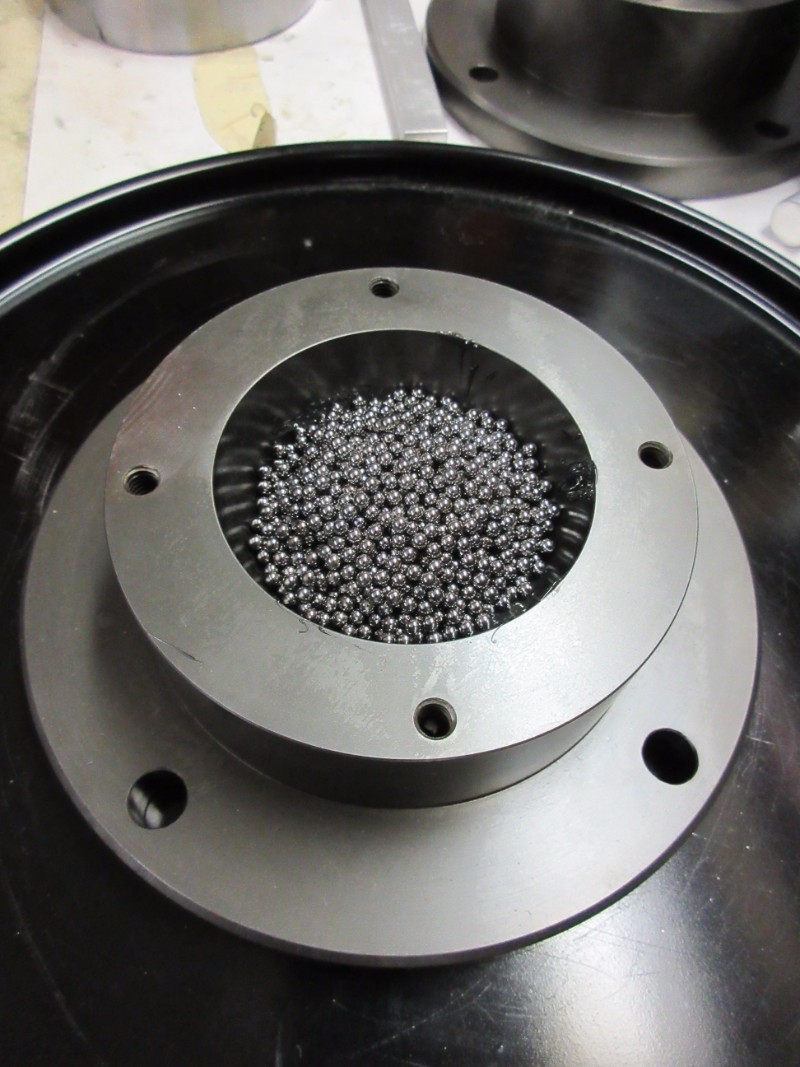
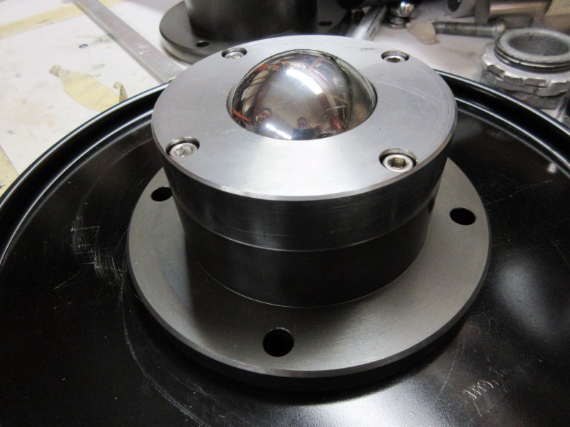
BL4N 35-deg bender magnet "No. 1" has been installed onto the magnet stand with "stand leg" configuration in the Proton Hall Extension loading bay area. The magnet fit as expected, and with the support legs resting on the ball transfers the magnet position could be easily adjusted by turning one of the adjuster leg fasteners (with the others loose). After experimenting with position adjustment, the fasteners were torqued to 70ft*lbs.
The engineering analysis (Document #138415) as well as drawings TBP1804, 1805, 1806, 1811, and 1820 are in the process of being updated to reflect all as-built changes.
|
|
Friday, May 15, 2015, 11:06, Isaac Earle, 100KW Beam Dump, Development, BD and Upper Pb Shield Water Hoses Replaced
|
The beam dump and upper lead shield flexible hose assemblies have been replaced with smaller diameter versions to allow for easier remote handling. The new beam dump hoses are TEL5501 (Rev A) & TEL5502 (Rev A). The new upper lead hoses are TEL5503 (Rev B) and TEL5504 (Rev B). All Swagelok joints were installed 1-1/4 turns past finger tight as per Swagelok instructions. The new Swagelok connections have not been leak tested yet. This will be done after the remote handling test of the vacuum seal and water block which is scheduled to begin on May 27th. |
|
Wednesday, June 10, 2015, 14:57, Isaac Earle, 100KW Beam Dump, Development, BD Water System Leak Test
|
A leak test was performed on the beam dump water system on June 9 in the afternoon.
- Pipe segments tested: The entire HAW system except for the expansion tank, air separator and HAW pump
- Test medium: air
- Test pressure and duration: 60 minutes at 50psi with no loss in pressure
- Swagelok joints and VCR joints around the beam dump which had been opened since last test were sprayed with Snoop: no bubbles |
|
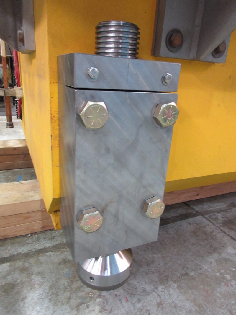
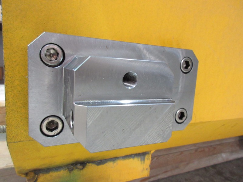
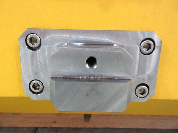
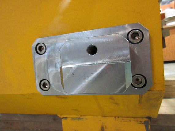
Wednesday, December 03, 2014, 10:45, Isaac Earle, 100KW Beam Dump, Development, BD Signals Traced from Service Stand to Junction Box
|
On Dec 2 the cables from the BD service stand area to the junction box were traced to establish which sensors correspond to which cable number in the junction box.
The beam dump thermocouple probe cable numbers are as follows (as labeled on the beam dump and the TC block upper half):
TC#1: T44, TC#2: T55, TC#3: T11, TC#4: T22, TC#5: T66, TC#6: T77
The service stand water sensor cable numbers are as follows:
Inside Tray, East Side: 44
Inside Tray, West Side: 22
Under Tray, East Side: 33
Under Tray, West Side: 11 |
|
Tuesday, April 18, 2017, 19:28, Jason Kapalka, T-Hall Crane, Development, ATH overhead crane fault investigation 8x
|
On April 18, 2017, an investigation was initiated to determine the cause of the ARIEL Target Hall overhead crane faults that occurred while attempting to perform remote lifting operations in Test Mode on a 8.6 tonne SEG block (see E-Log #30). Hugo Lapointe (Automation Technician, REEL-COH) requested pictures of the HIM (Human Interface Module) displays, located inside the electrical panels in the crane control room, immediately after a fault to assist with the troubleshooting process.
An unsuccessful attempt was made to trigger a fault in Test Mode with no load on the hook block. A 8.6 tonne load was then attached to the hook block and three separate fault incidents were quickly triggered, which are summarized below:
2017-04-18 2:12:57 PM 103. Main Hoist East Drum North Motor Drive Fault (700VFD) Fault Code: 211 Fault Description: Safety Brd Fault
2017-04-18 2:13:00 PM 104. Main Hoist East Drum South Motor Drive Fault (800VFD) Fault Code: 4 Fault Description: UnderVoltage
2017-04-18 2:13:00 PM 136. Main Hoist West Drum South Motor Drive Fault (900VFD) Fault Code: 4 Fault Description: UnderVoltage
2017-04-18 2:13:01 PM 135. Main Hoist West Drum North Motor Drive Fault (1000VFD) Fault Code: 4 Fault Description: UnderVoltage
2017-04-18 2:19:57 PM 136. Main Hoist West Drum South Motor Drive Fault (900VFD) Fault Code: 211 Fault Description: Safety Brd Fault
2017-04-18 2:20:00 PM 103. Main Hoist East Drum North Motor Drive Fault (700VFD) Fault Code: 4 Fault Description: UnderVoltage
2017-04-18 2:20:00 PM 104. Main Hoist East Drum South Motor Drive Fault (800VFD) Fault Code: 4 Fault Description: UnderVoltage
2017-04-18 2:20:00 PM 135. Main Hoist West Drum North Motor Drive Fault (1000VFD) Fault Code: 4 Fault Description: UnderVoltage
2017-04-18 2:23:07 PM 136. Main Hoist West Drum South Motor Drive Fault (900VFD) Fault Code: 211 Fault Description: Safety Brd Fault
2017-04-18 2:23:10 PM 103. Main Hoist East Drum North Motor Drive Fault (700VFD) Fault Code: 4 Fault Description: UnderVoltage
2017-04-18 2:23:10 PM 104. Main Hoist East Drum South Motor Drive Fault (800VFD) Fault Code: 4 Fault Description: UnderVoltage
2017-04-18 2:23:10 PM 135. Main Hoist West Drum North Motor Drive Fault (1000VFD) Fault Code: 4 Fault Description: UnderVoltage
It appears as though one motor causes the initial fault (Safety Brd Fault) and then the other three motors react to a safety trip fault (UnderVoltage). Upon further review of all the fault incidents from March and April it was observed that:
- 136. Main Hoist West Drum South Motor Drive Fault (900VFD) caused the initial �Safety Brd Fault� on 8 of 10 fault incidents
- 103. Main Hoist East Drum North Motor Drive Fault (700VFD) caused the initial �Safety Brd Fault� on 2 of 10 fault incidents
Pictures showing the 700, 800, 900, and 1000VFD HIM displays in FAULTED and normal mode were send to Hugo (COH) for review and are attached below. |
|
Friday, March 31, 2017, 19:39, Jason Kapalka, T-Hall Crane, Development, ARIEL Target Hall overhead crane faults (Test Mode)
|
On March 29, 2017, a 9 tonne steel shield block was transferred from the ARIEL Target Pit and placed into a
wood container on the Target Hall B1 level with the overhead crane main hoist in Local Mode without incident.
Afterwards, the overhead crane was switched into Test Mode (which is the same as Remote Mode but without the
Target Hall interlocked) and an attempt was made to transfer the shield block from the wood container on the B1
level to a wood container in the Target Pit remotely with the main hoist. At 11:51:09, after lifting the shield
block ~1 m above the B1 level, a "136. Main Hoist West Drum South Motor Drive Fault (900 VFD)" alarm pop-up was
shown on the overhead crane HMI in the crane control room which disabled the controls on the remote console.
The reset button on the remote console was pressed and the remote lifting operation was resumed briefly until
the same fault occurred at 11:51:42 and the reset button was pushed once again. While attempting to lower the
shield block back down to the ground this fault-reset sequence reoccurred at 11:57:25, 11:58:16, 11:58:28,
11:58:43, 11:59:27, and 12:00:27, at which point the remote crane operation was aborted and the shield block
was lowered down to the Target Pit floor with the main hoist in Local Mode, without incident. The Test Mode
faults did not appear to depend upon the speed/acceleration of the lift, nor did they appear to be spaced apart
by a fixed time interval. Upon closer inspection of the alarm history screen in the HMI (shown below) and the
exported alarm log (attached below), almost every time the fault #136 occurred, the following three additional
faults were logged simultaneously in the alarm history (but were not displayed as a pop-up on the main HMI
screen):
"103. Main Hoist East Drum North Motor Drive Fault (700 VFD)"
"104. Main Hoist East Drum South Motor Drive Fault (800 VFD)"
"135. Main Hoist West Drum North Motor Drive Fault (1000 VFD)"
On March 31, 2017, the overhead crane main hoist was operated once again in Test Mode; however, no load was
connected to the hook block to determine if the faults that occurred two days earlier could depend on the load.
The main hoist hook block was remotely lowered ~3 m below the upper 'home' position, and then remotely raised
as high as possible to function test the upper limit switch in remote mode; at 14:21:05 immediately after
initiating the 'hoist up' motion, the same four faults occurred simultaneously. This incident shows that these
specific faults do not depend on what load is connected to the hook block. Note: the crane position data from
March 31 is attached below, however the times shown are 1 hour fast due a DST adjustment error.
Follow up with the crane supplier, COH, is required to obtain a index and troubleshooting guide for these (and
all other) fault codes.
2017-04-06 update: Sylvain Raymond of COH has been assigned to resolve these crane faults by Maxime Dub�-Blanchet
of COH. |
|
Wednesday, April 12, 2017, 10:52, Jason Kapalka, T-Hall Crane, Repair, ARIEL Target Hall crane oil leaks & inspection plan
|
| On March 29, 2017, a 9 tonne load was transferred in the ARIEL Target Hall with the overhead crane (TRIUMF crane #44). On April 3, 2017, several drops of green oil were observed on the floor and hookblock directly beneath the single equalizing sheave. The Remote Handling department millwrights were notified and an inspection of the crane using a man-lift was performed to verify the source of the oil leak. Upon inspection, it was confirmed that the green oil leak was coming from the bearing on the single balancing sheave. This sheave wheel is rarely moved since it's primary purpose is to equalize the wire rope between the hook block and the two hoists; however both hoists have remained relatively synchronized since the crane installation in the summer of 2015. The millwrights suspect that the grease inside the sheave bearing has separated due to inactivity and the low viscosity fluid slowly weeps out. The leak rate was estimated at less than one oil drop per day.
During the inspection to find the source of the green oil leak, black oil was observed on top of both crane bridge girders. The apparent source of the black oil is the redundancy (aka failed drive bypass) system gearbox on the north and south side of the trolley. This black oil leak was significantly larger than green oil leak, and the question was raised about whether it was noticed during the annual inspection of the crane. Upon review, it was discovered that this crane was not yet added to the list of TRIUMF cranes that are inspected annually (typically performed during January-March), presumably due to its infrequent use. A request was made and this crane was added to the inspection list. Both leaks will be investigated further when the crane receives its annual inspection in April or May (which will be conducted by a third party service company) and the findings and recommended actions will be documented in this E-Log entry. |
|
Tuesday, May 16, 2017, 17:30, Jason Kapalka, T-Hall Crane, Development, ARIEL Target Hall Overhead Crane Measurements
|
| On May 5, 2017 the Beamlines and Remote Handling groups recorded distances in the ARIEL Target Hall from the Target Pit floor and B1 Target Hall floor elevations up to the overhead crane girders and main hoist rotation plate using a laser measurement device (see attached file).
On May 19, 2017, the Beamlines Group measured the B1 and Target Pit floor elevations relative to the Cyclotron centre (see attached file). |
|
Thursday, March 16, 2023, 14:41, Adam Newsome, T-Hall Crane, Development, ARIEL Target Hall Crane - Spare Pendant Procured, Tested
|
A spare pendant for the overhead crane was procured from COH. The pendant's functionality is the same as the original one's. The pendant was tested today by Adam Newsome - all functions behave as expected.
Important - to change to the spare pendant in the case of failure of the original one, insert a battery into it, and transfer over the small black transmitter card shown in the attached picture. The pendant will not pair with the receiver without this card. There is nothing else that needs to be set up for it to work.
The spare pendant is kept in a labeled box on top of the electrical cabinets located in the crane control room (L1 floor). |
|
Tuesday, April 25, 2023, 12:28, Adam Newsome, T-Hall Crane, Standard Operation, ARIEL Target Hall Crane - Drives Fault
|
Today while operating the crane with load, the crane stopped moving. Upon investigating, all safety signals appeared to be OK. Fault messages regarding drive faults for various VFDs were present, which seemed to stem from an ethernet adapter card fault (see attached photo). It is unknown how this occurred, but suspected that it was due to a brief blip in network communications or the external drive power supply control signal. It is worth noting that the diesel generator tests took place today, and there could have been some affect from a power surge because of this.
The crane was power-cycled using the main disconnect, and safety system reset. The faults disappeared. The crane was operational again.
If this issue occurs again, it should be investigated more thoroughly. It would be worth checking if there were any generator tests or other things which could cause some sort of power surge. |
|
Monday, March 10, 2025, 11:35, Jason Zhang, Hot Cell 1, Development, ARIEL Hot Cell PLC Update - 1000kg Crane Travel Zone
|
Wednesday, March 05, 2025, 13:00
Implemented and tested travel zone restrictions for the 1000kg crane to prevent collision with the manipulator arms. West operator station is currently occupied so testing was done and confirmed functional for the East operator station.
Movement of the crane is restricted and limited to only moving out of the zone in the following coordinates. Referencing the X and Y position to calibrate the encoder will bypass the zone restriction interlocks.
East Operator Station restriction Zones:
3048mm < X < 4601mm
1550mm < Y < 1680mm
Restrict +X When:
3048mm < X < Mid point (3824mm)
1550mm < Y < 1680mm
Restrict -X When:
Mid point (3824mm) < X < 4601mm
1550mm < Y < 1680mm
Restrict +Y When:
3048mm < X < 4601mm
1550mm < Y < 1680mm
-Y is not restricted because it is always a safe operation.
West Operator Station restriction Zones:
(TO BE ADDED LATER) |
|
Thursday, December 12, 2024, 15:57, Aaron Tam, Hot Cell 1, Development, APTW Pistons Gas lines exchange testing 13x
|
December 12, 2024 - Chad Fisher, Albert Kong, Aaron Tam
Tests:
Gas lines removal:
- Starting with the most exterior connection, VCR connection loosened off with open ended conventional wrench
- Once loose, the nut can be un threaded with manipulator finger (rolling nut technique)
- Once gas line unhooked, gasket removed by bringing female end outside the service tray footprint and jiggling until the gasket was removed
- Also possible to use a pick if needed
- The same procedure was conducted for the interior VCR connection
Gas lines installation:
- Starting with the inner most connection
- Gasket placed on 3D printed tool and clipped into position on VCR male end
- At first an M10 bolt was inserted into the elbow below VCR connection, but without rotational authority, the makeshift handle is not worth using
- Griping the elbow with one manipulator and rolling the nut onto the threads with the other proved successful
- Nut was tightened using conventional open ended 19mm wrench
Observations/Notes:
- Service Tray was not in a fully connected position, so even less space will be afforded.
- This may affect the ability to get 2 manipulators on the same connection
- Piston modules were missing some limit wires on the side. These constrain movement horizontally and will either need to be removed as part of the procedure or, make the procedure more difficult
- Mass markers and various other connectors not installed, and these could slightly restrict movement as well
- Service tray pin was restricting the movement of the left manipulator during install
- Lighting was inadequate under the piston
Recommendations/follow up items/questions:
- All metal Parker VGR style gaskets to replace plastic retainer versions
- This is so that the degraded plastic doesn't break off and end up in the gas lines (upside down connections)
- A modified wrench with flats for handles and with more length would make the above procedures easier
- Along with raising and lower the service tray, the service tray pin being oriented towards the beam entry direction, would make life easier
- Still need to test gasket install on "other" Piston gas line connection
- Chad will redesign some new gasket tools to be tested
- side load and axial load gaskets, low and high clearance, aluminum construction
- Lighting positioned to flood the service tray area will be needed
- labeling the gas lines with a more permanent solution will be needed
- Once the high voltage feed-through parts have come in, we can re-test and see if the piston module can be lowered to aid in target removal situations
- Aaron will test Parker style seals to see if they can be removed as easily once brought up to specified torque
------------------------------------------------------------------------------------------------------------------------------------------------------------------
December 16, 2024
- Upon inspecting the piston modules on AETE in TISA, we became aware of how the wires are arranged for the limit switches, it may be a good idea to look into how these wires are handled when using the piston module jig.
|
|
Wednesday, January 15, 2025, 13:52, Albert Kong, Hot Cell 1, Development, APTW Front End VCR Gasket Selection
|
Today RH (CF and AK) agreed upon using the following style of gaskets for the ARIEL front ends:
- All metal rings to be used to avoid plastic retaining rings deteriorating due to radiation and leaving bits stuck in the nuts
- Parker style (4 VGR-SS and 8 VGR-SS) gaskets for all VCR joints, except
- For the piston module and hanging water line VCR joints (found in the 'back', these should use SwageLok side-load gaskets (SS-4-VCR-2-ZC-VS and SS-8-VCR-2-ZC-VS)
- The primary reasons for which are clearance issues to fit normal loading VCR tools in these joints.
|
|