| |
ID |
Date |
Author |
Category |
Type |
Specific |
Subject |
|
|
250
|
Tuesday, April 16, 2019, 15:35 |
Keith C Ng | Repair | Other | M9 | M9 project post shutdown summary |
Completed work at m9 beam line:
- Removed existing service stand and associated cable and water services. Legacy b1 water services still need to be removed for future magnet installation. Old service stand is currently in warm cell waiting for disposal.
- M9 Q345 and vacuum roughing line were cleaned by CMMS group.
- M9 B1 is disconnected but remains in beam line ready for removal and refurbishment for 2020 shut down. Relevant ports have been sealed off.
- New Q1 Q2 baseplate was test fit and did not fit with guide post bolted in place, interferes with T2 port blank off plate.
- 3d lidar scans of magnet space were done.
- Leica tracker data was taken of the holes in the poured in place concrete pad.
Photos from shutdown are on remote handling group folder, under "\\trwindata\groups\remote handling\Photos\2019\2019 m9 project" |
|
|
258
|
Friday, February 28, 2020, 09:06 |
Isaac Earle | Development | Other | M9 | M9 Q1Q2 service stand floor plate installed |
The M9 service stand floor plate (TB23351) was installed in the M9 pit yesterday. Prior to installation all 5 threaded inserts were tested using a 1/2"-13 stud tool on an RH pole. The west most hole (shown in red below) had damaged threads and the stud could only be threaded in 2 turns. All other locations (shown in green) had usable threads with 6-8 full turns possible with the stud tool. The plate was installed using RH floor plate bolts (TB23382) at all four locations with viable threads. The bolts were torqued to 30 ft*lbs which on a bench test was shown to fully compress the belleville washer. The standard torque spec for 1/2"-13 stainless bolts (43 ft*lbs) was not used to allow easier disassembly in the future.
 |
|
|
260
|
Wednesday, March 11, 2020, 10:29 |
Isaac Earle | Development | Other | M9 | M9 Q1Q2 service stand foot plate installed |
The M9 Q1Q2 "foot" plate (TB23363) has been installed over the floor plate. A nominal gap between the plates of 1/2" was set before lowering the plate, it was then leveled using the three adjustment bolts resulting in a larger gap. After leveling, the plate was lifted to remove the spirit levels and lock the position of the leveling bolts. The plate was then re-lowered and the tiedown bolt assemblies (TB23383) were installed using 50ft*lbf of torque (about the maximum practical amount with standard 20' pole tools) |
|
|
262
|
Monday, April 06, 2020, 15:02 |
Isaac Earle | Standard Operation | Target 2 | M9 | M9 beam blocker returned to beamline |
The M9 beam blocker was returned to the beamline today using the RH shielded transport flask. The top flange o-ring was replaced before installation.
After installation the "Lift T" assembly was removed, and electrical cable and air supply connected. Correct functionality of the limit switches was confirmed with the control room. Actuation of the beam blocker could not be tested at this time because control takes place through the M9 area ASU.
|
|
|
263
|
Tuesday, June 09, 2020, 17:01 |
Isaac Earle | Development | Other | M9 | Cables and helium leak check line installed to M9 service stand |
The 10-pin thermal switch wire, 2-pin steering wire for Q2, and a 1/4" copper tube for remote helium leak check were installed through the service chase with the power cables and connected to the M9 service stand. Approximately 10m of extra cable (2-pin and 10-pin) was coiled and left in the cooler section of the service chase after the first sharp bend. The cables and the tubing are currently run as far as the vertical cable tray "waterfall" located near the M11 area. |
|
|
264
|
Wednesday, June 10, 2020, 08:58 |
Isaac Earle | Development | Other | M9 | T2-M9 and M9-B1 flange scan data |
Laser tracker scan data from 2017 and 2019 attached as a backup. Original files from Beamlines Group who also keep copies on \\trwindata\experimental support\alignment\T2-M9_data |
| Attachment 1: 2017-03-28_meson_hall_t2_with_import_of_2015_data.xit64
|
| Attachment 2: 2019-25-01_meson_hall_t2_data.xit64
|
|
|
265
|
Friday, June 12, 2020, 13:54 |
Isaac Earle | Development | Other | M9 | M9 Q1Q2 water header installed |
The Q1Q2 water header (TB23481) was mounted this morning as per installation drawing TB23400.
Heat shrink tubing was applied to the B1 power cables (two positive, two negative) over the length of cable in the highest field which was showing some signs of radiation damage on the insulation. The tubing used was McMaster-Carr PN 75665K932 (Clear PTFE, 4:1 shrink ratio, 1.0" ID before shrinking), as recommended by Syd Kreitzman. Each piece of tubing is 4' long, and two were used per cable. The first one was shrunk along its full length, then the second piece was only shrunk where it overlaps the first and the remainder was left loose. This was done to minimize time required in the high dose area.
Hand-stacked concrete bricks were removed from the location where the new piping will run to the water header. This is scheduled to take place between July 6-8 |
| Attachment 1: 2.jpg
|

|
| Attachment 2: 1.jpg
|

|
|
|
266
|
Tuesday, July 07, 2020, 13:22 |
Isaac Earle | Development | Other | M9 | M9 Q1Q2 |
The M9 Q1Q2 magnet assembly lift beam has been installed according to drawing TB23401. The side-to-side as well as beam-axis direction adjustment features were tuned so that the assembly is level when lifted.
Aug 5, 2020 update: All fasteners on the lift beam assembly have been torqued according to the specification on drawing TB23401
|
| Attachment 1: 8.jpg
|

|
| Attachment 2: 1.jpg
|

|
| Attachment 3: 4.jpg
|

|
| Attachment 4: 6.jpg
|

|
|
|
267
|
Tuesday, July 07, 2020, 15:13 |
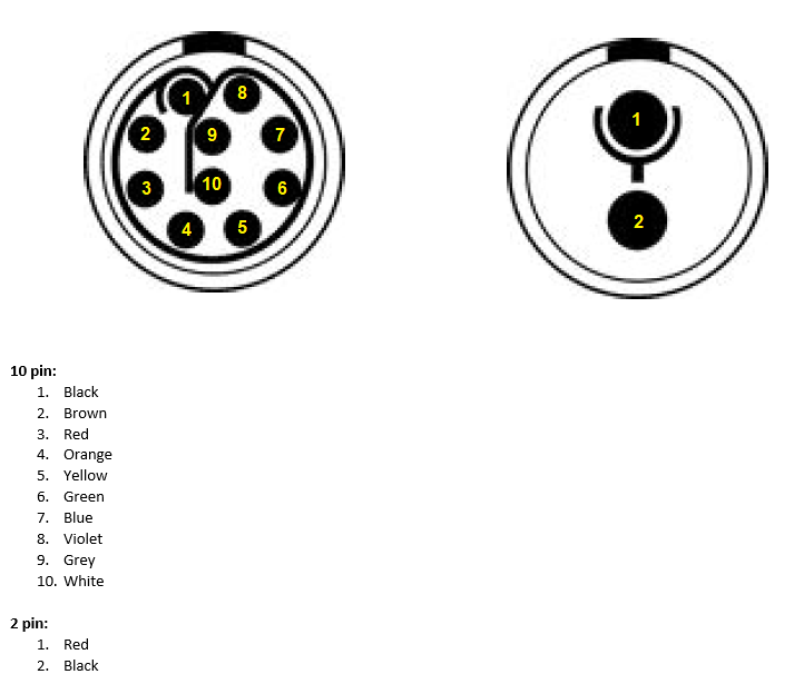
Isaac Earle | Development | Other | M9 | M9 Q1Q2 service stand Lemo connector wiring |
The diagram below shows the wiring for the two connectors on the service stand (the wires running from the stand to the power supplies. (see TB23400 for details)
|
|
|
268
|
Thursday, July 09, 2020, 06:44 |
Isaac Earle | Development | Other | M9 | Alignment of M9 Q1Q2 magnets complete |
Mike Vogel reported that alignment of the Q1Q2 assembly w.r.t. the T2 and B1 flanges was completed on July 7. This was performed in the test stand with the flange positions set to the measurements taken in the 2019 shutdown. Alignment to the theoretical location was achieved within 0.1mm.
The axis of the Q1 and Q2 magnets were aligned to each other previously within similar accuracy. |
|
|
289
|
Wednesday, May 04, 2022, 11:27 |
Adam Newsome | Standard Operation | Target 2 | M9 | M9 and M20 Beam Blocker Actuation Test |
The beam blockers for M9 and M20 were actuated, and vacuum was monitored to ensure no disruptions. Both actuation tests were successful. Motion was observed and no abnormalities noted. Cabling and air connections checked: OK.
Note: there was a safety interlock issue with M9 which prevented actuation - a relay or fuse was temporarily removed from the safety system ~10 years ago but it was not replaced. It was replaced for the purpose of this test, and then removed again. |
|
|
366
|
Thursday, May 01, 2025, 13:25 |
Riley Sykes | Repair | Other | Indium pump | Indium Extruder |
Indium extruder Double acting cylinder repairs and service complete. Adjustments were made to relief valve setting on pump model P84 as PSI was too low in combination with old cylinder seals and pump was dumping to reservoir. Advance and retract stroke both acceptable, tested with mock indium gasket and extruder working as designed. |
|
|
296
|
Wednesday, July 06, 2022, 12:49 |
Adam Newsome | Repair | Other | Hot Cell | Hot Cell - Helium wand tubing broken |
The tubing for the helium wand inside the hot cell is broken and needs to be replaced. More tubing has been ordered and the job will be completed in the coming weeks. |
|
|
297
|
Wednesday, July 06, 2022, 12:52 |
Adam Newsome | Other | Other | Hot Cell | Potential hot cell window oil leak |
Some oil was noticed around the hot cell window, on the control panel, and on the ground below the control panel. A leak is suspected.
Suggest tightening all bolts to specified torque along the window, and monitoring overflow oil level (position today was marked). If the problem persists, the gasket must be replaced. Note that the gasket should likely be replaced anyway as it has not been done for some time. |
|
|
298
|
Thursday, July 28, 2022, 12:51 |
Adam Newsome | Repair | Other | Hot Cell | Meson Hall Hot Cell - Nuclear Ventilation Issue |
It was reported today by Peter Bratt that the nuclear ventilation system for the hot cell is not functioning. At this time, the cause of the issue is unknown. Remote Handling and Electrical Services are investigating. This e-log will be updated when the issue is resolved.
Update: the issue was caused by worn belts which had been smoking. The belts must be replaced. |
|
|
301
|
Tuesday, August 30, 2022, 14:24 |
Adam Newsome | Maintenance | Other | Hot Cell | Nuclear Ventilation - Filter Change |
Mechanical Services Group changed the pre-filter in the ventilation system on Aug. 29, 2022 as per work permit C2022-08-29-2.
It is recommended that Mechanical Services change the HEPA filter as soon as possible. These filters are on order with approximately 7 month lead time.
Edit: as of 2023-05-03, the HEPA filter has been changed. |
|
|
328
|
Wednesday, May 03, 2023, 10:06 |
Adam Newsome | Maintenance | Other | Hot Cell | Meson Hall Hot Cell - Nuclear Ventilation HEPA Filter Changed, Operational |
The HEPA filter in the nuclear ventilation system for the Meson Hall Hot Cell was changed and tested by mechanical services under work permit C2023-04-25-14.
They have given approval to operate again. The system is re-energized. |
|
|
342
|
Thursday, February 01, 2024, 11:14 |
Albert Kong | Standard Operation | Target 1 | Hot Cell | T1-MK1 Flush and Purge on Hot Cell |
The recently removed T1-MK1 target ladder was flushed with city water for ~30s at all target positions. It was then purged with compressed air at ~5 psi for ~1 minute at all target positions. We then left the target ladder in pos5 to fully extend the bellows and allow it to dry overnight.
This ELOG will be updated as we progress with work done to dry the target ladder and eventually exchange the spent targets.
-----------------------------------
UPDATE (Feb 02, 2024): in the morning, the target ladder was moved to pos4, and air was allowed to run through the morning, in the afternoon the ladder was moved to pos2 and air was ran. At the end of the day, the ladder was moved to pos 0 and air was ran through over the weekend.
-----------------------------------
UPDATE (Feb 05, 2024): the following procedures were completed.
- the air connections on the target ladder was replaced with the leak test/vacuum connections as per instructions.
- LN2 was taken from the ISAC-I facility and used to perform two pump-down cycles with the Agilent He leak detector + cold trap.
- First pumpdown cycle: 3min45sec to go from roughing to fine pumping, left for a total pumpdown time of1hr20mins, a relatively small amount of ice formed on the cold trap cylinder (see image).
- Second pumpdown cycle: 2min30sec to go from roughing to fine pumping, 4min30sec to reach 1e-3 Torr, 5min to reach < 1e-3 Torr.
- Due to good pumpdown in the second cycle, we proceeded with leak testing: Baseling 1.0e-10 Torr-L/sec | ~1 sec He applications at 3.5 Psi directed at fittings/welds/bellows. Worse case measured leak was 0.9e-7 Torr-l/sec in pos 13 of fig 12 of Document 46600 (see taken image for detailed measurements at various locations).
We will prepare an update to the procedure to better log the leak rate measurements and update this ELOG/the procedure. Note that ice removed from second pumpdown was actually comparable to the first (see image, ice knocked off during cold trap removal), but total pumpdown duration (including leak testing) was ~4 hours for the second pumpdown.
UPDATE (Feb 13, 2024): see attached record with new template.
|
| Attachment 1: IMG_3950.JPEG
|

|
| Attachment 2: IMG_3975.JPEG
|

|
| Attachment 3: IMG_3973.JPEG
|

|
| Attachment 4: IMG_3971.JPEG
|

|
| Attachment 5: T1&T2_Pump-Down_and_Leak_Check_Record_05_FEB_2024.pdf
|


|
|
|
344
|
Thursday, February 15, 2024, 12:38 |
Riley Sykes | Repair | Other | Hot Cell | Indium Extruder Hand Pump |
Feb 1 2024
Hand Pump observed to be losing pressure at full extension of cylinder, seals likely blown. Due to Enerpac P84 being an obsolete model, a newer model hand pump was ordered.
Feb 15 2024
Hand pump (Enerpac P84 Ultima) installed at Indium Extruder Station, observed to work properly in both directions of flow, deemed operational. |
|
|
355
|
Thursday, October 10, 2024, 12:24 |
Adam Newsome | Other | Other | Hot Cell | Safety Walkaround Complete - Meson Hall HC/WC Area |
A safety walkaround was completed for the Meson Hall Hot/Warm Cells.
The resulting spreadsheet can be found on DocuShare as Document-242733.
Main deficiencies identified:
- Hot Cells:
- Pressure gauge reading is suspect
- Operator station phone not working (resolved now)
- General:
- Lifting equipment has overdue inspection
Action has been taken on all deficiencies.
|