 Wednesday, September 12, 2018, 15:30, Isaac Earle, North Hot-Cell, Development, , , Installation of NHC operator-level lighting completed Wednesday, September 12, 2018, 15:30, Isaac Earle, North Hot-Cell, Development, , , Installation of NHC operator-level lighting completed 
|
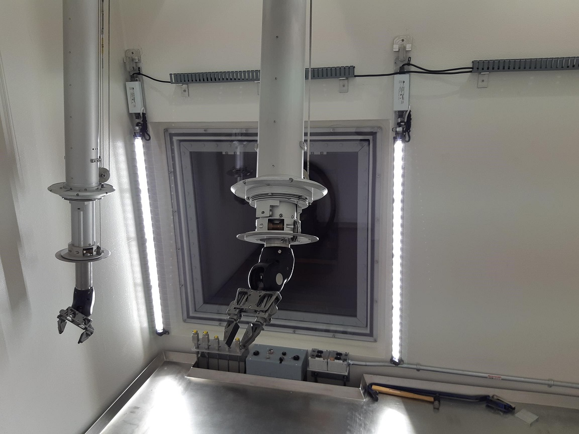
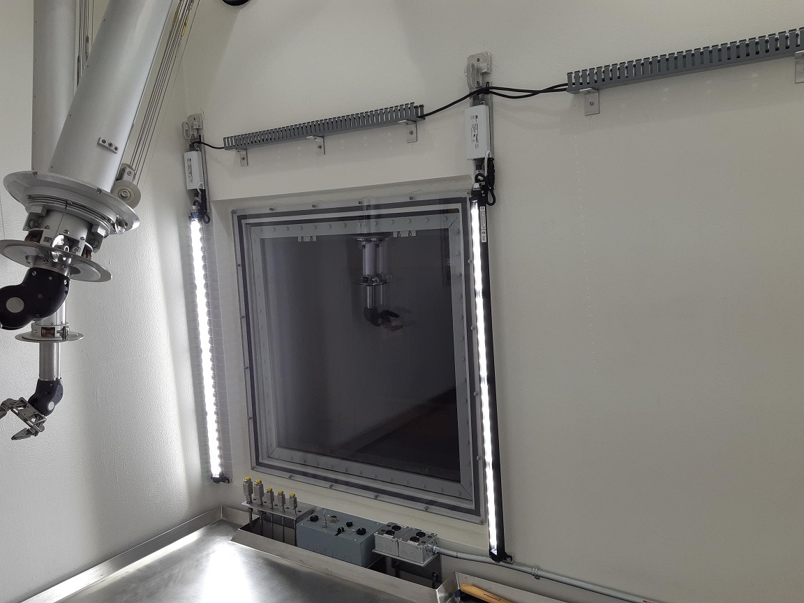
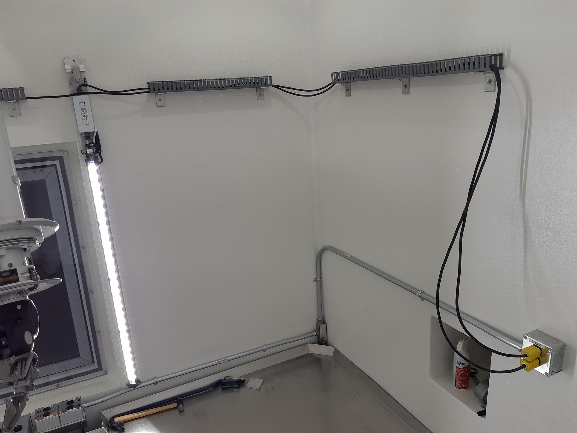
Installation of of operator-level lighting in the NHC was completed today according to drawing IRH1801. 2" x 2" Panduit was mounted to the wall on aluminum brackets to support the power cables. These lights can be replaced remotely by unplugging the power cords using the manipulators, lifting the cable out of the Panduit with a hooked pole tool through the manipulator slave end removal roof hatch, lifting the light fixture off the support bracket with the pole tool, then installing a new fixture in the opposite order. This RH procedure will be tested at a later date as part of NHC commissioning.
|
|
Thursday, September 13, 2018, 16:57, Isaac Earle, North Hot-Cell, Development, , , NHC grounding and mili-ohm testing
|
The following equipment has been connected to the building ground located in the Target Hall by the TCS using 1/2" flat bonding strap:
- NHC roof structure
- NHC/TCS partition wall
- NHC work table
The following equipment has been connected to the building ground by connecting to the work table inside the NHC using 1/2" flat bonding strap:
- Air and gas supply line mounting bracket inside NHC
- Receptacle box mounting bracket inside NHC
- Diagnostic signal box mounting bracket inside NHC
The resistance between the following locations and the copper grounding plate located at the base of the NHCSA north wall were measured. The resistance of the wire used was 258.10mΩ, and has been subtracted from the following results.
Measurements taken in NHCSA:
- Control panel below viewing window (base plate of box): 4.67mΩ
- Oil window frame (bare metal drain valve): 55.34mΩ
- Left manipulator (ground plate near e-stop button): 73.46mΩ
- Right manipulator (ground plate near e-stop button): 202.58mΩ
- Air and gas supply line mounting bracket: 40.68mΩ
- Diagnostic connector box: 12.15mΩ
- Steel conduit for 110V supply to hot cell interior: 4.81mΩ
Measurements taken inside NHC:
- Work table: 4.51mΩ
- Pre-filter bolted to partition wall: 4.84mΩ
- Table hatch lid: open load
- Left manipulator thru tube: 515.8mΩ
- Right manipulator thru tube: 342.0mΩ
- Left manipulator (slave boot plate bolt): 885.9mΩ
- Right manipulator (slave boot plate bolt): 1444.0mΩ
- Grounding strap for air/gas plate: 4.84mΩ
- Outside of SHV connector on diagnostic signal box: 4.56mΩ
- Exterior of 110V electrical conduit: 3.88mΩ
- Male Staubli connector for 1st gas line: 53.7mΩ
- Welded stud for window cover panel: 6.06mΩ
- Grounding strap for partition wall: 4.39mΩ
- Roof structure (measured inside un-painted bolt hole): ~0mΩ
- Stainless steel module flange: ~0mΩ
Dedicated grounding will be added in the near future for the oil window frame and the manipulator thru-tubes. Testing will then be repeated for those items.
Dec 18, 2018 update:
The oil window frame and both manipulators (where they bolt to the thru-tubes) were connected to the building ground using 1/2" flat bonding strap connected at the cold side of each piece of equipment, and running to the grounded copper sheet located in the NHC service area at floor level. The connection is made inside the electrical racks located directly west of the NHC operator area on the cold side. This work was done by Travis Cave in October 2018.
Mili-ohm testing for these items has not yet been repeated.
Jan 14, 2019 update:
Grounding was added from the metal plate near the e-stop button on the master arm of both manipulators. The same 1/2" flat bonding strap was used which was tied into other bonding strap which runns to the grounded copper sheet in the NHCSA.
Mili-ohm testing was repeated for the following items:
- Oil window frame (bare metal drain valve): 13.6mΩ
- Left manipulator (ground plate near e-stop button): 16.1mΩ
- Right manipulator (ground plate near e-stop button): 16.5mΩ
|
|
Thursday, November 22, 2018, 14:38, Isaac Earle, North Hot-Cell, Development, , , NHC design approved by High Voltage Engineer
|
To satisfy RS 101 from the NHC requirements specification (Document-131915) Tomislav Hurskovec was consulted regarding high voltage safety. After a verbal discussion on various aspects of the NHC design he confirmed that the design satisfies high voltage safety concerns.
A copy of his confirmation e-mail is attached in PDF format.
|
|
Monday, November 26, 2018, 12:19, chad fisher, North Hot-Cell, Repair, , , East Manipulator
|
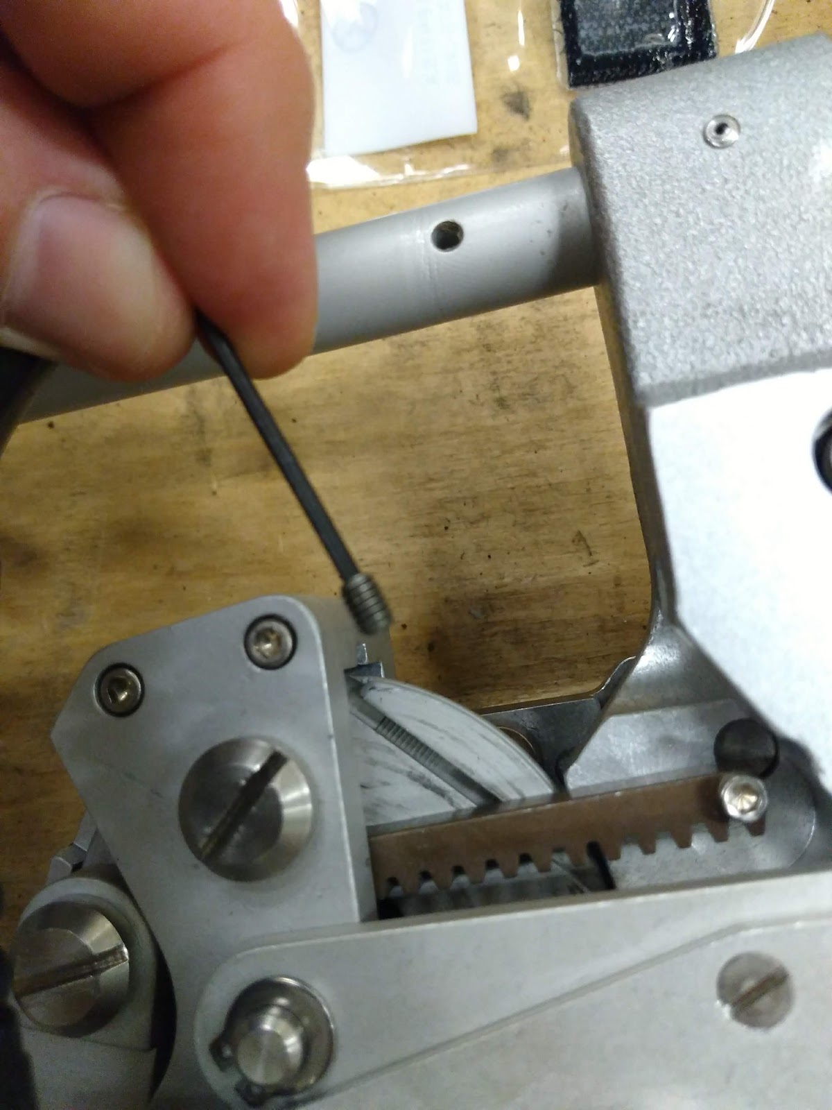
In preparation for removing the slave for replacement I discovered that the timing screw in the handle cable drum (master side) had been left threaded into the pulley...it should have been completely removed. It was bent from hitting on a casting inside the mater arm which most likely contributed to the hopped pulleys on the slave side. After removing this timing screw I entered the north hot cell and replaced the hopped cable back onto its pulley and Isaac tested the motions that previous caused the hopped cables. These tasks were repeated 4 times without any issues. Also of note is a missing setscrew in the tong cable pulley pin and a somewhat loose tape on the slave, also the tape shows signs of a crimp/bend. Upon further inspection and comparison with the other slaves I also found that one of the "lock-down" fittings tying the Z motion tape drum to the corresponding gear is completely missing. See pictures attached. |
|
Friday, December 07, 2018, 08:47, chad fisher, North Hot-Cell, Repair, , , North hot cell spare slave repair
|
The tong cable on the spare north hot cell slave has been repaired. Slave came from the factory with the tong cables straddling one of the pulleys they are suppose to run through.
|
|
Friday, December 07, 2018, 10:37, chad fisher, North Hot-Cell, Repair, , , Ariel connector test
|
Completed testing of connectors for Ariel using the north hot cell.
Video can be found on docushare; document 161909 |
|
Monday, December 10, 2018, 15:31, Isaac Earle, North Hot-Cell, Development, , , NHC remote connection testing with manipulators
|
The following tests have been successfully completed using the NHC manipulators:
- Ventilation pre-filter (mounted on the NHC/TCS partition wall) removed and re-installed using the manipulators
- Electrical plugs (two total) for operator-level LED lighting located on east wall of cell interior plugged in, and un-plugged using the manipulators
- Electrical plug inserted into and removed from each of the 120V outlets (four total) located in front of the viewing window using the manipulators
- All diagnostic service connections removed and reinstalled using the manipulators (six total, see IRH1765)
- All Staubli air and gas connections removed and reinstalled using the manipulators (five total, see IRH1749)
These tests were performed at various different times over the last several months by Isaac Earle and/or Chad Fisher. |
|
Tuesday, December 18, 2018, 11:13, Isaac Earle, North Hot-Cell, Development, , , NHC manipulator slave-end swap, RH test, and various other work
|
The following North Hot Cell work was completed over the last week under work permit I2018-12-12-1:
Thurs Dec 13th:
- Prepared master side according to removal manual (noticed screwing in the right side locking screw was not as smooth to go in as normal; left side was smooth like normal)
- Removed manipulator roof block and set down in yellow frame (required some stacked wood to prevent light from bottoming out)
- Removed steel side plates in NHC manipulator hatch
- Removed the slave end (SN: 9764) – noticed “Right Elevation/Twist Coupler” off of vertical by around 30 degrees
- Wrist elevation of removed slave end was not locked, lifted it slightly and this brought the coupler to the vertical position and it locked with a click
- Suspected the thru-tube also would be misaligned, confirmed by inspecting visually in hot cell (Unsure why this misalignment occurred considering we followed the removal procedure properly. One theory is that when we accidentally left the timing screw in the master side handle cable drum last time it may have caused things to get a little out of alignment)
Friday Dec 14th:
- Un-did the right side locking screw on the master
- Then could turn coupler on the thru-tube to the vertical position from within the hot cell
- Re-locked the right side locking screw (this time it went in smoothly)
- With all couplers on thru-tube vertical we then installed the replacement slave (SN: 9352) as per instructions
- For future slave end changes should use some sort of long chain or sling instead of having the auxiliary crane hook block within the hatch (some sort of T-hook type lift feature replacing the bail may work better as well)
- Evaluated the manipulator: seemed to be working normally, Chad tested plugged in LED lamp plug and also opened and closed the work table hatch
- Noticed Z motion tape on slave end loose when fully extended in Z (nice and tight when retracted) – this seems to be normal
- Confirmed manipulators can reach all surfaces of the table
- Then tested remote handling of LED light fixtures from the Target Hall using pole tools through the manipulator roof hatch
- Started with both LED light plugs un-plugged
- Used 9’ standard beam lines RH pole tool (this worked fine, but 10-12’ would be better)
- Curved hook end attachment
- First lifted cables out of all cable tray sections (the wall mounted Panduit)
- Then removed the East light fixture assembly (IRH1800) - lifted from designated lift loop (IRH1796) – This went smoothly
- Hoisted up into the Target Hall, then lowered back down to re-install
- To reinstall had to hook the assembly at a lower point due to flex of the pole from the weight of the assembly (hooked just below the ballast for installation). Using this method reinstalling the fixture went smoothly. I will update the design to move the designated lift point (or add an additional one) at this location.
- Once the light fixture was on the bracket, replaced the cables in the cable tray using the pole tool. The final section on the east wall before the outlets was a little tricky, but by viewing and reaching from the north-west corner of the hatch it was do-able
- Confirmed visually that remote removal and installation of the west fixture can be done using the same procedure as the east
- Replaced lamp block (stored lifting hardware for hatch side plates above block, below hatch cover)
Monday Dec 17th:
- Left side slave-end boot was installed as per manual instructions. It was done with two people inside the cell this time which went much smoother than just one last time (the boot was not installed on the slave prior to moving it into the hot cell because we wanted to inspect the tape and cables after installation and the boot would prevent that)
- The condition of both boots was checked. Both appear to be in new condition with no signs of degradation. The material seems pliable and strong.
- Chad Fisher, ISAC Hot Cell Operator, checked the light level from the cold side of the hot cell and confirmed that it is acceptable. However, without the operator level LED lighting it was too dim.
Tuesday Dec 18th:
- Lift bails for both manipulator slave ends set to farthest north position which results in face that mates with thru-tube to be close to vertical when hanging from lift bail
- Work table, stairs, entrance floor area, pre-filter assembly, tool port, window cover, and hot side service connection panel vacuumed and wet wiped to remove dirt and dust.
- NHC inlet damper (located in Target Hall) adjusted to set NHC depression to around 1.05”wc (the NHC damper is currently not responding to the NVCS and needs to be investigated and repaired by Controls Group and/or Mechanical Services)
|
|
Friday, January 04, 2019, 14:38, Isaac Earle, North Hot-Cell, Development, , , NHC cameras tested
|
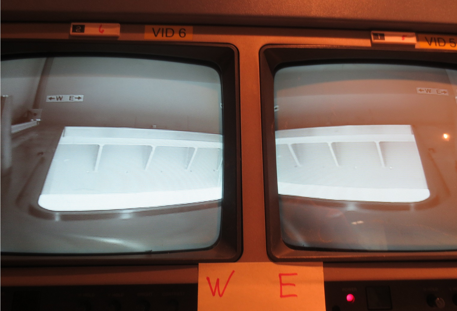
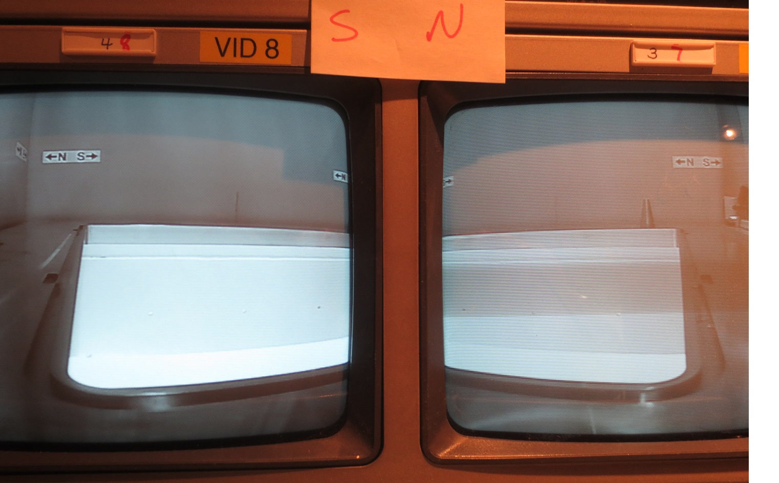
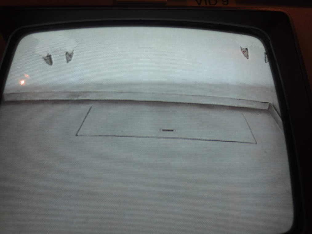
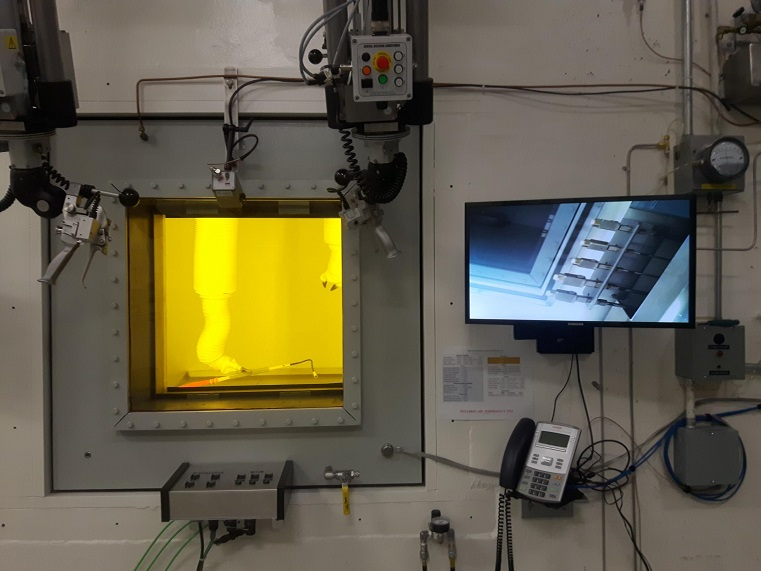
The NHC module support flange cameras (4 total) as well as the NHCSA camera were tested today and confirmed to be working properly. All cameras were angled and focused properly, and displaying clearly on the monitors in the ISAC RH Control Room. Photos of the control room monitors are attached below.
 |
|
Friday, January 18, 2019, 10:26, Isaac Earle, North Hot-Cell, Development, , , NHC sealing improvements and repeat of RH test for LED lights
|
The following NHC development work was completed under WP I2019-01-09-4:
- Location of RH feature on operator level LED lighting updated to match IRH1800 Rev B design
- Remote Handling test of the LED fixtures was repeated using a 9' pole with hook attachment through the manipulator slave hatch from the Target Hall: both LED fixtures were removed and reinstalled successfully with relative ease
- Tool port seal replaced to address an audible air leak: the 1/4" foam seal was removed and replaced with adhesive backed 5/8" wide hollow foam rubber seal (McMaster Carr PN: 93085K81). Prior to the change DPG4 was at 0.63"wc, after the change wit was 0.73"wc with all system variables constant.
- NHC manipulator access block seal was replaced, likewise to address an audible air leak: the 1/4" foam seal was removed and replaced with adhesive backed 1/2" thick BunA-N rubber strip (McMaster Carr PN: 9023K85). DPG4 was at 0.94"wc prior to the change, and 1.07"wc after with all system variables constant
|
|
Monday, January 21, 2019, 16:27, Isaac Earle, North Hot-Cell, Development, , , NHC in-cell camera wired to right side monitor
|
The NHC right side monitor has been wired to display the signal from the in-cell camera. This was tested using a snake camera on both of the CPC-4 connectors.
|
|
Thursday, January 31, 2019, 14:16, Isaac Earle, North Hot-Cell, Development, , , NHC grounding approval
|
Franco Mammarella was consulted regarding electrical grounding of the NHC design (RS103 of Document-131915). After discussing the design, and having grounding inspected by Randy Boehm, Franco approved the design and advised that the grounding system should be inspected periodically. This task has been added to the Remote Handling inspection index on an annual schedule. A PDF copy of the e-mail correspondence with Franco is attached. |
|
Thursday, February 27, 2020, 16:08, Anders Mjos, North Hot-Cell, Maintenance, , , Hot Cell Entry
|
Chad entered the NHC today to tighten set-screws on both slave side manipulators and re-align the West side slave. Work took place using the HC Confined Space Entry procedure. See attached checklist. WP I2020-02-27-4 |
|
Friday, March 27, 2020, 08:45, Matthew Gareau, North Hot-Cell, Maintenance, , , Issues with the manipulators
|
This is a link to all of the issues with the NHC manipulators that I know of
https://documents.triumf.ca/docushare/dsweb/View/Collection-27663/Document-180176
|
|
Tuesday, October 27, 2020, 11:46, Matthew Gareau, North Hot-Cell, Repair, , , Ratcheting repair issues with both left and right master
|
The were issues with both left and right master ratcheting;
- the left handle was getting stuck in a close position when there was a higher ratcheting tension added
- the right ratcheting was not tightening preventing proper use of the manipulator
Chad and myself were able to identify a missing set screw for the tong cable.
Once this was added the issue with the left master ratcheting seems to be solved.
Lubricant was added to the left master ratchet and this seems to solve this problem as well.
There was also an observation of missing set screws on the spare manipulator for attaching the wrist to the ratcheting handle, which will need to be ordered and attached.
|
|
Thursday, December 24, 2020, 09:00, Matthew Gareau, North Hot-Cell, Development, , , NHC USB connection
|
24/Noc/2020
USB was discovered to be in the reverse direction and will need to be change around to become operational
01/Dec/2020
USB was pulled from conduit
While attempting to re-pull the USB in the correction direction, the ethernet cable was damaged and need to be replaced,
(thanks to the Hubert's team for the wire help)
It was decided that it was too problematic to re-pull the wires with all other wires in the way. Therefore all the wires were removed from the operator control panel, and pulled so that the USB, USB power cord, and ethernet could be re-pulled all together.
However, even once all the wires were re-pulled and reconnected it was discovered that the USB had become damaged, and was removed again.
23/Dec/2020
- A new conduit was added through to the NHC, for only the USB
- USB was fed through, reconnected, and tested
- Putty will need to be added around the conduit to ensure a good seal into NHC |
|
Thursday, March 04, 2021, 16:30, Isaac Earle, North Hot-Cell, Development, , , NHC gas delivery lines leak checked
|
The North Hot Cell gas delivery lines (labeled 1, 2, and 3 on the hot and cold side panels) were leak checked today. 5psi helium gas was applied to each line in turn with the appropriate solenoid valve opened and a Staubli connector with plastic tubing and the leak check wand attached to the matching connector inside the cell. The end of the wand was sealed using tape. The Agilent G8601 leak detector was used on "sniffing" mode to check for escape of helium gas from all joints and connectors. With the sniffing line attached the leak detector test port pressure was 3.9E-1 Torr and the baseline leak rate was 1.7E-6 Torr*L/s. There was no response while testing all of the three lines. For all three there was a leak detector response after disconnecting the Staubli fitting, which confirmed that the lines were properly charged with helium. |
|
Friday, March 05, 2021, 09:12, Matthew Gareau, North Hot-Cell, Development, TM3, , Containment box door removal and swivel arm test
|
First thing I entered into the NHC to install to the target kart mounting clip, and remove excess tools and materials from the hotcell
After the TM3 without a target was lowered into the NHC.
Once inside, with the use of the manipulators, I was able to remove the containment box door, place it on the swivel arm, move the arm out of the way, after the door was return to the containment box and reattached.
|
|
Tuesday, May 25, 2021, 15:59, Matthew Gareau, North Hot-Cell, Development, , , Removed boot from left hot manipulator 7x
|
Myself and Isaac removed the boot from the left hot manipulator.
- opened the hatch in the TH to get access to the top of the boot
- released the latch on the boot and loosened the boot from above
- closed TH hatch
- with the right manipulator we were able to detach the rest of boot
This test proved that we can remove a boot from the manipulator without having to enter into the hotcell.
Due to the physical restraints that the boot causes for the operator, we have decided to not reattach the boot with its current design.
A new design will be investigated to allow the boot to be fixed without twisting, which is the source of the problems.
|
|
Wednesday, June 09, 2021, 09:16, Travis Cave, North Hot-Cell, Standard Operation, TM2, no target, Module move
|
TM#2 has been moved from the SHC to the NHC. |
|