| ID |
Date |
Author |
Category |
Type |
Module |
Target/Number |
Subject |
|
2010
|
Tuesday, October 22, 2019, 16:26 |
Isaac Earle | Safe Module Parking | Development | | | SMP shield box grounding |
A braided grounding strap was attached to the aluminum gear box support on the SMP shield box structure, and grounded by attaching it to the exterior of an electrical conduit located in the south-west corner of the B2 area at the top of the silo in that corner. The braiding was also connected to the stainless steel support structure for the SMP vacuum pump. |
|
2016
|
Monday, October 28, 2019, 12:00 |
Isaac Earle | Safe Module Parking | Development | | | SMP shielding attenuation measured & compared to theoretical values |
The attenuation of the SMP shielding was measured as part of SMP commissioning (Document-170404, R1, Section 4, Test #8)
The field on the shutter side of TM3 was measured without any shielding as it was removed from a storage silo. At 0.5m from the edge of the module the maximum field was 5.00mSv. After installation into the SMP the maximum field outside the SMP shielding at 0.5m from the edge of the module was found to be 27uSv/hr. The resulting attenuation is 185x
Expected attenuation was calculated by Joe Mildenberger assuming that the majority of the activated components in that module are either copper or aluminum. With 6" of steel shielding (SMP shield vessel plus vacuum vessel), the attenuation factors were found for the following isotopes:
Na-22 (created in Al): 115
Co-60 (created in steel (Fe) or Cu): 70
Mn-54: (created in steel (Fe) or Cu): 200
Based on these figures, the measured result of 185 seems to be reasonable. |
|
2037
|
Thursday, December 12, 2019, 14:39 |
Isaac Earle | Safe Module Parking | Development | | | SMP assembly shifted 1.0" north |
The SMP assembly was shifted approximately 1.0" north today by pushing it, braced against the south wall, using a 100 Ton capacity air lifting bag supplied by Beamlines Group. The move was one of the action items identified at the Gate 4A/4B close-out review. During commissioning of the SMP, TM3 was installed into the vacuum vessel, which required the crane to be all the way at its south limit, so the move is to provide some margin for future use, particularly if TM1 is put in the SMP as the extent of its shielding is slightly larger than the other modules.
One of the air fittings for the lid actuation cylinder on the north side was damaged during the move. It was replaced and correct functionality of lid actuation was then confirmed. |
|
2196
|
Thursday, March 04, 2021, 16:30 |
Isaac Earle | North Hot-Cell | Development | | | NHC gas delivery lines leak checked |
The North Hot Cell gas delivery lines (labeled 1, 2, and 3 on the hot and cold side panels) were leak checked today. 5psi helium gas was applied to each line in turn with the appropriate solenoid valve opened and a Staubli connector with plastic tubing and the leak check wand attached to the matching connector inside the cell. The end of the wand was sealed using tape. The Agilent G8601 leak detector was used on "sniffing" mode to check for escape of helium gas from all joints and connectors. With the sniffing line attached the leak detector test port pressure was 3.9E-1 Torr and the baseline leak rate was 1.7E-6 Torr*L/s. There was no response while testing all of the three lines. For all three there was a leak detector response after disconnecting the Staubli fitting, which confirmed that the lines were properly charged with helium. |
|
2200
|
Monday, March 15, 2021, 13:01 |
Isaac Earle | Crane | Development | | | Plate & pin lift assembly load testing (ITA6550) |
In mid-2020 design analysis was completed on the steel plate & pin assemblies (ITA6550) used to connect the ISAC target hall crane hook block to the module lifting yoke assembly ITA0494. The released design note is Document-184431.
In November 2020 fabrication was completed on two full plate & pin assemblies (photos attached below). As per the relevant ASME standards (identified in the design note), each assembly has been identified with serial numbers (#1 and #2). Material test reports for the steel plate and round bar material used for fabrication are attached in PDF format. For both materials the tested tensile yield strength (from the MTR) exceeds the value used in design calculations (from Document-184431): 117ksi vs 100ksi for the plate material; 138si vs 103ksi for the round bar material.
On February 8, 2021 both plate and pin assemblies were load tested by David Wang and Frank Song. The total load applied to each was 31,400 lbs (as per the ISAC target hall crane load cell) which exceeds the 125% of rated capacity (31,250 lbs) required for the test. The lifts were conducted successfully and no deformations or other damage to the assemblies were observed. Photos of the load test are also attached.
Both plate & pin assemblies are now certified for use up to their rated capacity. As specified on drawing ITA6550 and in Document-184431, a monthly visual inspection must be performed to check for structural deformation, cracks, excessive wear, and loose or missing fasteners. In addition, an annual inspection must be performed to check for structural deformation, cracks, excessive wear, loose or missing fasteners, and missing or illegible markings or safety labels. A written record of the annual inspection must be documented and kept readily available.
|
|
68
|
Tuesday, January 10, 2012, 11:51 |
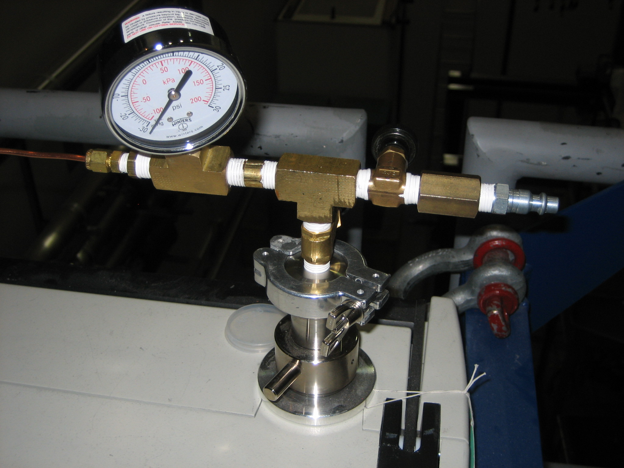
Grant Minor | Conditioning Station | Repair | | | IMC at Cond. Station is VENTED - DO NOT PUT MODULE IN |
Hi Remote Handling,
The guage on the IMC circuit in the Target Hall is reading atmosphere, and the bellows is currently relaxed (i.e. expanded), whereas it should be reading about -20inHg and the bellows should be contracted (i.e. compressed).
I've attached a photo of what the guage and fittings should look like when pumped down to -30inHg.
Either the IMC circuit has been vented, disturbed, or it has some kind of leak. When I was in the Target Hall this morning, I saw the gauge bent around the railing at an awkward angle with a pretty severe bend in the copper line, it appeared to have been disturbed by the temporary glove box sitting at that level used by Rob Walker for nuclear ventilation work.
I will co-ordinate pump-down and leak check of the circuit, but the Conditioning Station cannot be used until this is repaired.
Cheers,
Grant
 |
|
129
|
Wednesday, June 20, 2012, 11:39 |
Grant Minor | South Hot-Cell | Development | TM3 | N/A | TM3 Planned Activites at South Hot Cell Jun 20 to 29 2012 |
|
(Copy of e-mail correspondence sent June 20th 2012)
After some discussions this morning I’ve decided on the following best path forward for TM3 at the Hot Cell leading up to the Canada Day long weekend.
General Goals:
- Blank-off TM3 water line terminations (coil, heat shield, water-cooled window)
- Test sliding tray removal tool to determine fit on TM3 chassis
We will skip the Conditioning Station leak tests and return TM3 directly to a silo for the following reasons:
- We will have a visitor next week and this will impact Chad’s time available to do Hot Cell work
- Helium pressure leak checks on the blanked-off circuits are only one small portion of a large set of diagnostic tests (leak, electrical, HV, etc.) that must ultimately be performed on TM3 to determine its fitness. This full set of tests must be carefully documented in a procedure and executed systematically when there is adequate time at the CS to do all of them, with results recorded. There is currently not adequate time for this work between now and Canada Day.
- If we were to detect a leak from one of these tests, it would not tell us anything about where the leak is in that given circuit (there are multiple possible points). The service cap would have to be opened regardless, which we don’t have time for.
- The aforementioned bullets above lead me to conclude that the extra work required for two module moves for one set of partial leak checks is not a value-added exercise: In other words, the module will have to go back to the CS, regardless of what we do over the next week for more tests. The time savings of trying to squeeze it in next week are really negligible and it makes for a tight schedule for not much benefit.
Chad: Please prepare a detailed work plan for your hot cell jobs including a list of the tools required and what leak checks you will do specifically after you have installed the blank-offs. You may refer to existing procedures if you already have these written. I would like to review this plan and I am expecting that an e-log will be filed daily and this work plan should be referred to as an attachment.
Proposed Schedule Jun 20 to 29
Wednesday Jun 20 (1 working day)
- Setup for TM3 move from Silo to HC (Travis, David)
Thursday Jun 21 (1 working day)
- TM3 moved from silo to HC (Travis, Don Dale, David)
Friday Jun 22 to Wednesday Jun 27 (4 working days)
- Chad performs the following HC work on TM3:
· Removes containment box
· Installs water-line blank-offs
· Checks Sliding Tray Removal Tool Fit
- Vacuum leak checks of blanked-off lines at the HC (Chad, David, VG)
- Chad buttons up TM3
- In parallel - David performs block moves as required
Thursday Jun 28 (1 working day)
- TM3 moved from HC to Silo (Travis, Don Dale, David)
Friday Jun 29 (1 working day)
- Contingency
RH Group: Please move ahead with the work as outlined above. Please comment if you have any concerns or proposed changes to this plan. Thanks very much to all for your assistance,
Grant
-------------------------------------------------
Grant Minor, M.A.Sc., P.Eng.
TRIUMF Remote Handling Group Leader
Nuclear Engineer
4004 Wesbrook Mall, Vancouver
BC, Canada, V6T2A3
gminor@triumf.ca
(604) 222-7359
http://www.triumf.ca/profiles/4557
------------------------------------------------- |
|
148
|
Wednesday, July 18, 2012, 16:49 |
Grant Minor | South Hot-Cell | Development | | | South Hot Cell Ventilation Alarm Trip |
Today (Wednesday July 18th) at around 4:15 pm I was taking a small tour group from VECC into the Target Hall. In the process of discussing the mechanical design of the Target Modules and South Hot Cell turntable I inadvertently lifted the Aluminum Hatch Cover of the Hot Cell about 2 inches in an effort to explain something. This tripped the ventilation alarm before I realized what I was doing. I evacuated the visitors from the Target Hall, checked booties and gloves at the check station before having the visitors step over the boot box. I called operations and let them know what I had done. The Target Hall was locked out and is awaiting a survey for the morning of July 19th before work can proceed. |
|
149
|
Wednesday, July 18, 2012, 16:49 |
Grant Minor | South Hot-Cell | Development | | | South Hot Cell Ventilation Alarm Trip |
Today (Wednesday July 18th) at around 4:15 pm I was taking a small tour group from VECC into the Target Hall. In the process of discussing the mechanical design of the Target Modules and South Hot Cell turntable I inadvertently lifted the Aluminum Hatch Cover of the Hot Cell about 2 inches in an effort to explain something. This tripped the ventilation alarm before I realized what I was doing. I evacuated the visitors from the Target Hall, checked booties and gloves at the check station before having the visitors step over the boot box. I called operations and let them know what I had done. The Target Hall was locked out and is awaiting a survey for the morning of July 19th before work can proceed. |
|
218
|
Monday, December 03, 2012, 19:34 |
Grant Minor | ITE | Standard Operation | TM4 | LpUCx | Argon supply opened for ITE vent |
Around 7pm tonight I opened the main valve approximately 1.5 turns on the Argon bottle used for venting ITE, located in the ISAC electrical room. The cylinder pressure gauge increased to about 1500 psi. I adjusted the secondary regulator (pressure relief valve) until it read 2psi. I opened the needle valve in the vent line completely. The pressure on the pressure relief valve dropped slightly and I adjusted it again until it read 2psi. The Argon supply should be ready for venting ITE w/ TM4. The station should be vented around midnight to prepare for TM4 disconnect tomorrow morning. If there are problems with the venting process, an operator should check the pressure on the secondary regulator / pressure relief valve to ensure it is reading 2psi. - Grant Minor |
|
222
|
Wednesday, December 05, 2012, 13:26 |
Grant Minor | South Hot-Cell | Standard Operation | TM4 | N/A | TM4 moved from SHC to South West Silo |
TM4 was successfully moved from the South Hot Cell to the South-West Silo remotely by Grant Minor, with help from David Wang and Don Jackson. The move was without problems. See ISAC Work Permit 2012-12-04-1. |
|
238
|
Friday, January 18, 2013, 16:56 |
Grant Minor | Conditioning Station | Standard Operation | TM4 | | VAT valve btwn roughing and nuc. vent. closed |
Bevan attempted to start pumping down on TM4 today remotely but there was an issue. He will report on Monday.
I went into the Target Hall this afternoon while on the phone with Bevan and performed the following:
- Checked the knurled vent valves on the side of each turbo, both were found to be in the tightened position (all the way clockwise)
- Closed the VAT valve between the scroll pump and the nuclear ventilation |
|
239
|
Friday, January 18, 2013, 17:01 |
Grant Minor | Conditioning Station | Development | TM4 | | Photos of the CS with TM4 (after the no-module HV test, only vacuum connected) |
Attached are some photos of TM4 in the Conditioning Station after the no-module HV test completion. Only vacuum services are connected. |
|
243
|
Friday, February 08, 2013, 11:42 |
Grant Minor | ITE | Maintenance | | | TAPC 477 resolved - ISAC elec. room gas cylinder |
See attached TAPC 477 documentation. |
|
423
|
Wednesday, August 21, 2013, 20:36 |
Grant Minor | South Hot-Cell | Repair | TM3 | | TM3 module-side water block sealing surface inspection (post polishing) |
The water block sealing surfaces on the module-side of TM3 were polished this week by Chad Fisher, using his air-ratchet controlled rotating head tools (single and double-surface polishing tools).
Photos of the polishing tools in-use are attached (from August 16 - 21, 2013)
Scotch-brite pads were used, followed by 2000 grit sandpaper, then white felt with isopropanol, then lint-free dry polishing pads, each on detachable heads that are used with the polishing tool.
The module-side water block surfaces were inspected by Grant Minor on 21 Aug 2013 using a level telescope and camera looking through the hot cell window. Results can be viewed here, with photos indicating which block is being viewed in sequence.
https://documents.triumf.ca/docushare/dsweb/View/Collection-11251 |
|
424
|
Thursday, August 22, 2013, 19:38 |
Grant Minor | South Hot-Cell | Repair | TM3 | | TM3 Rev 3 source tray - water blocks connected and torqued |
After a great struggle with the water block jigs, the TM3 source tray was finally advanced fully into the service tray and all water blocks were connected and torqued to spec in the hot cell by Chad Fisher.
Notes and description of problems encountered during the installation:
- The water lines for the optics tray interfered with the module-side water block jig, and had to be bent out of the way to clear while advancing the tray (see attached photos)
- The water block jig on the source tray side was too low relative to the module side, and had to be eventually unbolted completely from it's mounting bracket in order to raise it up into alignment
- A piece of aluminum plate was placed under the jig, and the pneumatic table was raised in order to move the jig upwards
- After many repeated attempts to engage the blocks by pressing the jigs together, it was discovered that some of the blocks had rotational misalignment with their respective counterparts on the module side, preventing the pins from engaging properly
- By looking through the bolt holes on several of the blocks, it was possible to determine which direction they had to be rotated
- Chads polishing tool was used to apply some torque to rotate the source-tray-side water blocks slightly so proper alignment of the pins could be achieved
- See the attached photo which indicates which blocks had to be rotated (blocks 5, 6, 9, 10, and 11)
- The blocks had the bolts installed and were also torqued in the numbered order shown in the attached photo
Next steps are to remove the water block jigs, re-connect the loosened brackets for the remaining water lines (entrance window, optics tray), re-install the containment box and associated VCR connectors, video inspect, and leak check. |
|
425
|
Friday, August 23, 2013, 18:32 |
Grant Minor | South Hot-Cell | Repair | TM3 | | TM3 Rev 3 - steerer wire broken from connector on module side |
While continuing on the TM3 Rev 3 source tray installation, Chad noticed today that one of the steerer wires is broken and has come out of the thermocouple-style connecter block (see attached photos).
From drawing ITA2826 (Rev D02 attached) it is likely that this is for either the "upper" or "right side" steerer plate. |
|
426
|
Monday, August 26, 2013, 18:22 |
Grant Minor | South Hot-Cell | Repair | TM3 | | TM3 Rev 3 - all connetions made except steerers, IMG, and entrance window |
Today Chad finished making all connections to the new source tray, except for:
- steerers - broken wire, must be repaired at a later date
- IMG gauge - bracket required, old bracket thrown out with previous tray by accident, see ITA3301, must be installed at a later date
- entrance window - the window lines on module side were left blanked-off for leak checking, containment box must be removed in the next few days to complete steerer repairs so these lines were not connected to save work from having to be repeated
The containment box was replaced, and TM3 was moved to the CS for pump-down and leak checking (see other e-log). David reported at 6:15 pm that the turbos were turned on at the CS and the vacuum looked normal (so far).
As stated above, Chad realized today that he had thrown out the old IMG gauge bracket with the previous source tray, and a new one must be manufactured. The assembly is described by ITA3301. Three components must be manufactured (ITA3302, ITA3303, and ITA2673). A stock split-ring clamp for ITA2673 (MDC #716001) was graciously donated by Dimo Yosifov. Grant Minor submitted a work order to the machine shop today for 2 each of ITA3302 and ITA3303. |
|
427
|
Monday, August 26, 2013, 18:26 |
Grant Minor | Conditioning Station | Standard Operation | TM3 | | TM3 moved from Hot Cell to Conditioning Station |
Target Module 3 with no target, and a partially-installed Rev-3 source tray (no steerers connected, no IMG connected, entrance window lines blanked off on module side and not connected to containment box) was transported successfully to the Conditioning Station by Travis Cave and David Wang at around 4pm today. David attached the vacuum system for start of pump-down to prepare for leak checking. |
|
431
|
Tuesday, August 27, 2013, 17:18 |
Grant Minor | Conditioning Station | Repair | TM3 | no target | TM3 Rev 3 source tray - prelminary leak check results at CS |
David Wang started a helium leak check on TM3 at the CS this morning.
David will create an e-log once his check is complete, but here are the preliminary results:
- target oven +/- OK
- mounting support plate OK
- ionizer tube heater +/- OK
- extraction electrode OK
A large leak was found in the heat shield circuit:
- The module pumped down with the leak rate stabilizing at 4.8xE-9 atm.cc/sec
- 60 psi helium was applied to the heat shield fitting on the right side of the Y-shaped connector (see attached sketch, each side of the "Y" is separated by a face to face metal contact only, i.e. no o-ring seal separates supply and return water)
- The maximum leak response was detected in 10 seconds, with base pressure rising from 2.0E-2 torr to 2.8xE-2 torr
- The helium was vented from the line by using an allen wrench to open the valve on the water quick-connect (see attached photo)
- The module continued pumping down, and after some time, the allen wrench was used again to open the valve, but air rushed inside, indicating vacuum was being drawn inside the water line through the leaking interface
- As the module continued to pump, this vacuum vent air rush inside the water line could not be reproduced by opening the valve again with the allen key
The module is currently pumping down at the Conditioning Station. We will leak check the remaining lines tomorrow with whatever base leak-rate we have achieved, and then move TM3 to the Hot Cell for further diagnosis. |