 Wednesday, September 07, 2016, 11:39, Isaac Earle, North Hot-Cell, Development, , , NHC North / South Wall Gap Measurements Wednesday, September 07, 2016, 11:39, Isaac Earle, North Hot-Cell, Development, , , NHC North / South Wall Gap Measurements
|
Measurements were taken today of the NHC north/south wall gap at the location where the NHC/TCS partition wall will be installed (43.375" from the NHC west wall). A HILTI PD40 laser range meter was used for the measurements. They were taken at 10", 34", 62", 90", 118", and 142" from the floor which matches the top of each cross-beam. The results are below:
10" from floor: 102.44"
34" from floor: 102.40"
62" from floor: 102.48"
90" from floor: 102.63"
118" from floor: 102.28"
142" from floor: 102.24"
Based on these results a partition wall plate width of 102.00" will be used for the bottom two plates, and 102.25" for the upper three plates in order to keep the gap on each side approximately 1/8" |
Thursday, September 15, 2016, 11:05, Isaac Earle, North Hot-Cell, Development, , , NHC / SHC feedthrough panel removed 
|
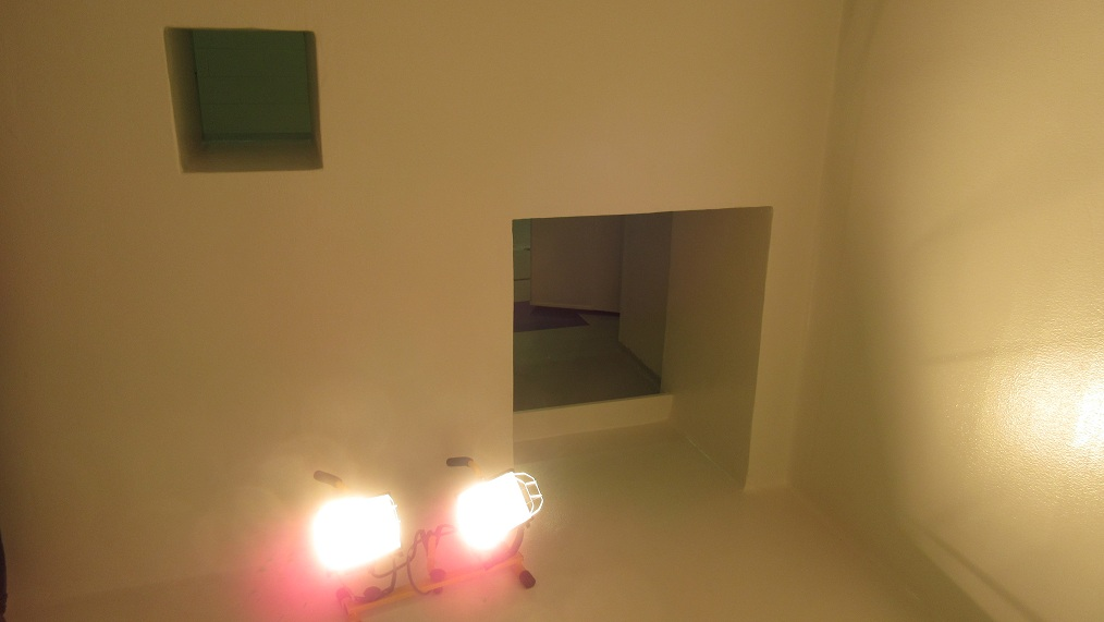
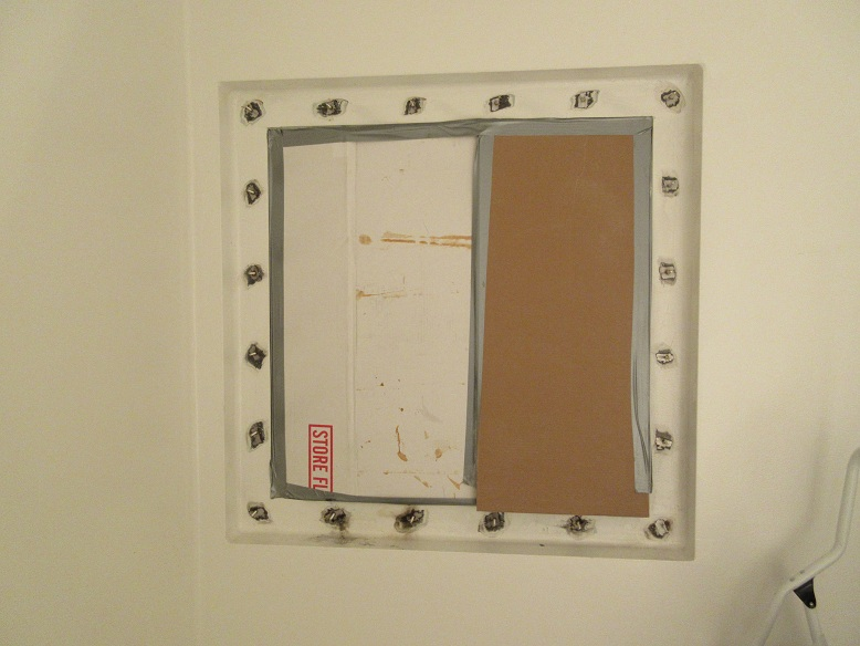
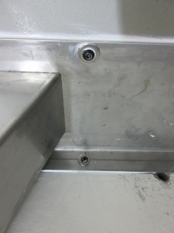
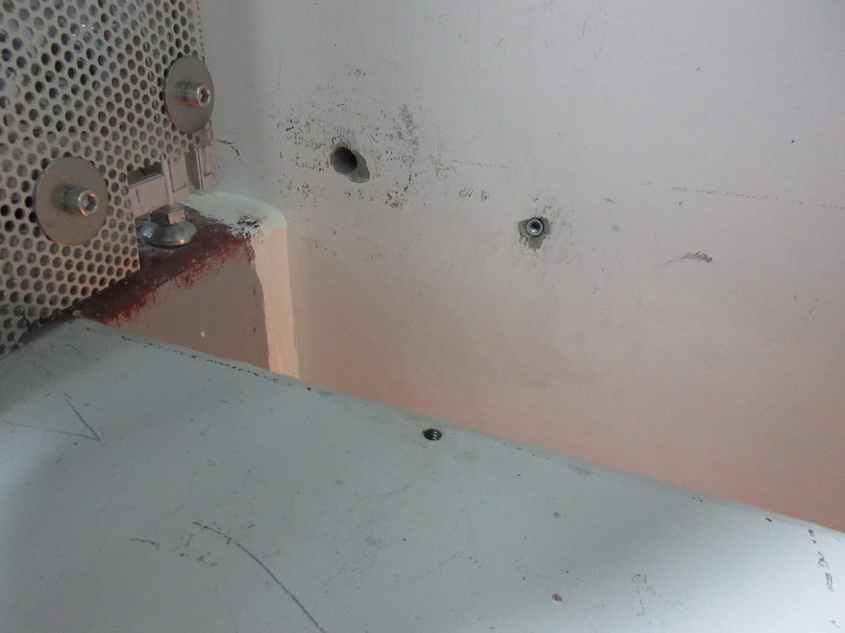
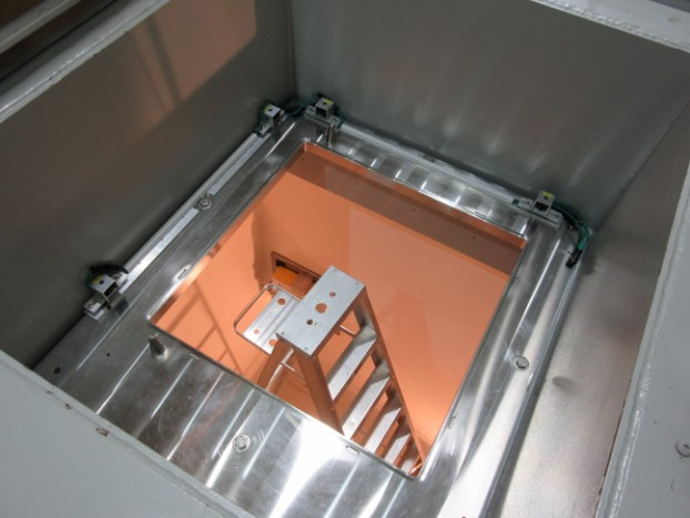
The sheet metal panel covering the NHC/SHC feedthrough port was removed today using a slide-hammer to pull out the concrete anchors (this oversized panel would have interfered with the NHC partition wall). 50cpm was found on the inside of the panel, 100cpm on the NHC side lip of the feedthrough, and 350cpm on the face of the shielding bricks in the feedthrough. Various dimensional measurements of the feedthrough were taken which will be added to the partition wall Solidworks model (IRH1609). The panel was bagged for disposal and a temporary 20"x20" panel was put over the feedthrough and secured with duct tape. A permanent panel with anchored supports that is compatible with the NHC partition wall will be designed and installed at a later date. A swipe of the NHC walls and floor picked up 30cpm after completion of the job. |
|
Tuesday, November 08, 2016, 14:04, Isaac Earle, North Hot-Cell, Development, , , Interference check with TCS turbo pump and proposed NHC duct routing
|
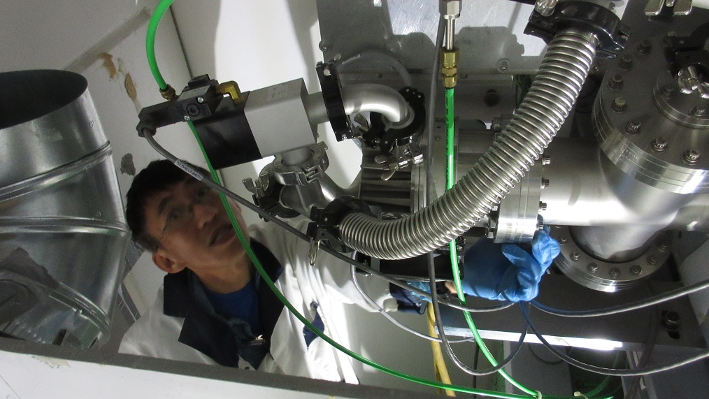
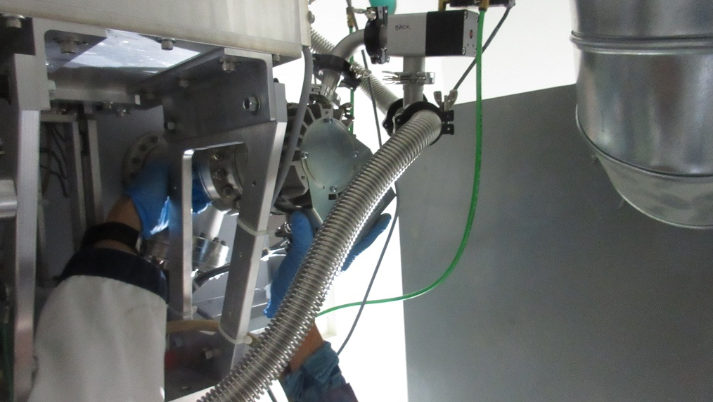
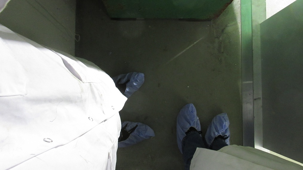
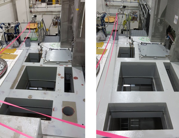
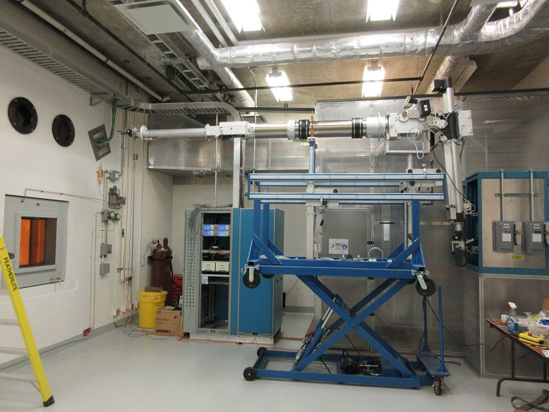
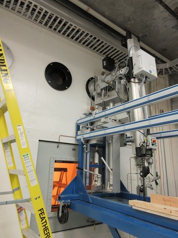
David Wang and I accessed the NHC today to check if the proposed duct routing (IRH1618) will interfere with servicing or replacement of the TCS turbo pump. A piece of plywood was placed in the future position of the NHC/TCS partition wall (IRH1609), and a ducting elbow was placed at the approximate position of the nearest elbow to the turbo pump.
David concluded that the ducting in the proposed location will not have any significant effect on replacement of the turbo pump, and he does not expect replacement will be difficult to perform after installation of the wall and NHC ducting. Standing at floor level towards the east side of the TCS space and reaching upwards seemed to be the best way to reach the turbo pump flange bolts. It was also noted that there was sufficient room in the TCS space for two workers to be in the area.
|
|
Friday, December 09, 2016, 14:58, Isaac Earle, North Hot-Cell, Development, , , NHC service area floor and top of roof block painted
|
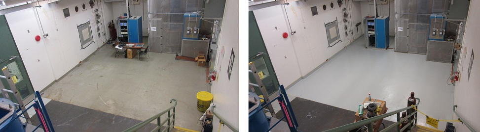
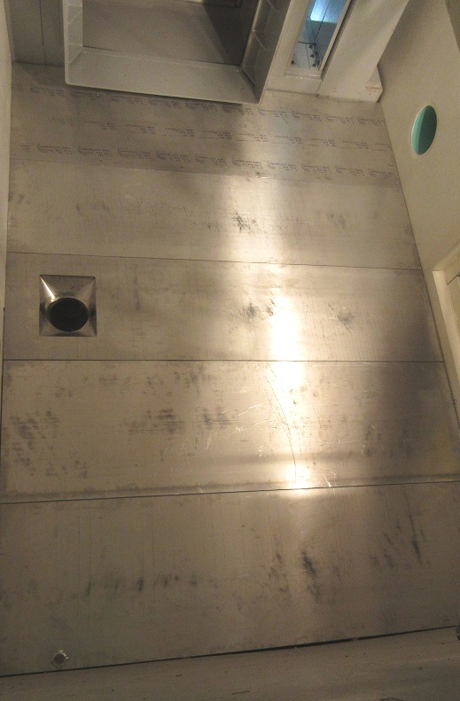
The concrete floor in the North Hot Cell service area and the top of the NHC roof block in the target hall have been painted with Macropoxy 646 oil based epoxy paint, colour Flint Grey. Two coats were used for the NHC roof, and one for the service area floor.
|
|
Tuesday, January 17, 2017, 13:45, Isaac Earle, North Hot-Cell, Development, , , NHC ducting installed
|
The new ducting section connecting the existing duct termination in the TCS space to the NHC partition wall has been installed by Smith Sheet Metal contractors. The installation drawing is IRH1618. There was not enough clearance between the duct pipe and the TCS vessel to butt weld the new ductwork as originally intended. Instead a flange was welded to the existing pipe and also to the new section and the two were bolted together. Drawings of the modifications have been provided by the contractor, and as-built drawings will be completed at a later date. There was not time for the contractor to fabricate a gasket for the flanged joint, so one will be installed by TRIUMF at a later date and included in the as-built drawing package. |
|
Wednesday, January 18, 2017, 11:53, Isaac Earle, North Hot-Cell, Development, , , NHC partition wall installation complete
|
The final panels of the partition wall were installed today as per drawing IRH1609. Sealing, finishing, and painting of the NHC walls and floor can now commence.
|
|
Tuesday, February 07, 2017, 15:57, Isaac Earle, North Hot-Cell, Development, , , Ventilation Ducting Gasket Installed
|
Lead gasket IRH1633 was installed today according to assembly drawing IRH1618 Rev B. |
|
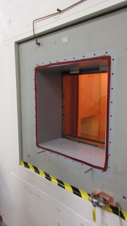
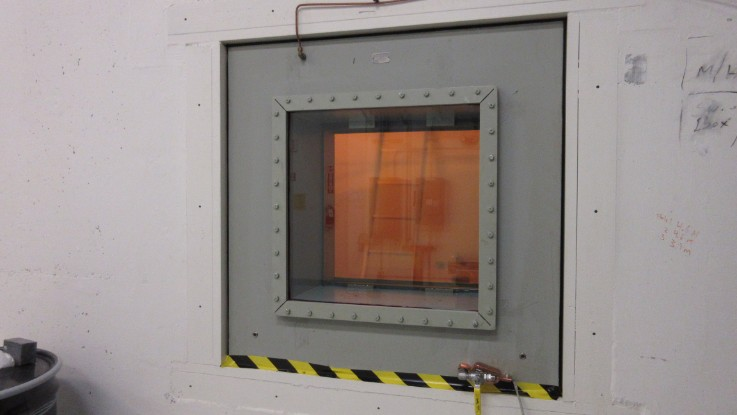
Thursday, February 09, 2017, 14:07, Isaac Earle, North Hot-Cell, Development, , , North Hot Cell Shielding Window Gaskets Changed 23x
|
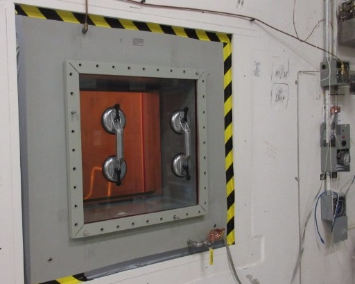
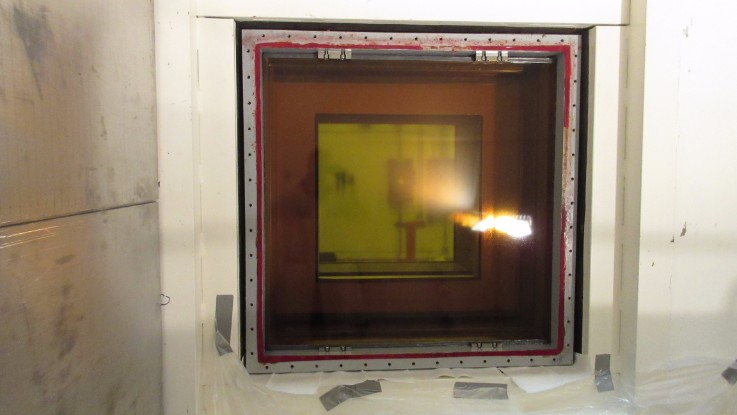
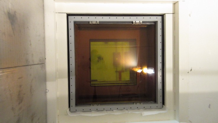
The North Hot Cell shielding window gaskets have been changed and the window has been filled with new oil. Although there was no noticeable oil leaks before starting the job, the gaskets had not been changed since initial installation approximately 15 years ago, so they were done now as part of construction of the new cell. The work took place between January 26 – Feb 8, 2017 following the attached PDF “Full procedure for NHC shielding window gasket change” which references “Gasket change procedure from Hot Cell Services” (also attached).
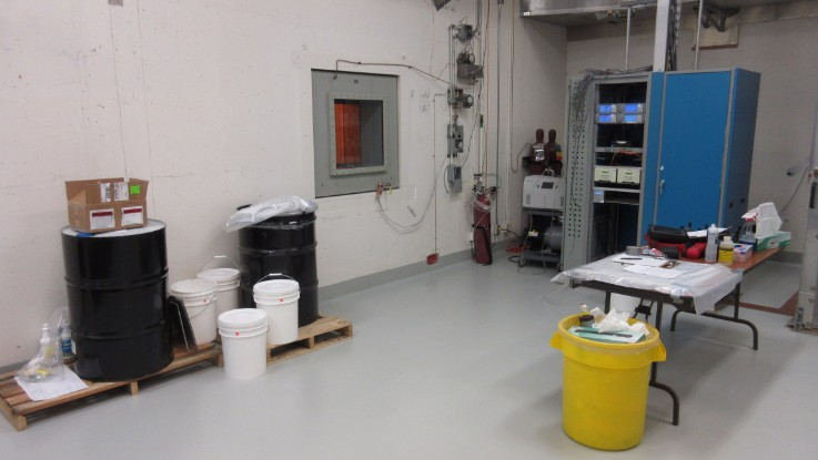
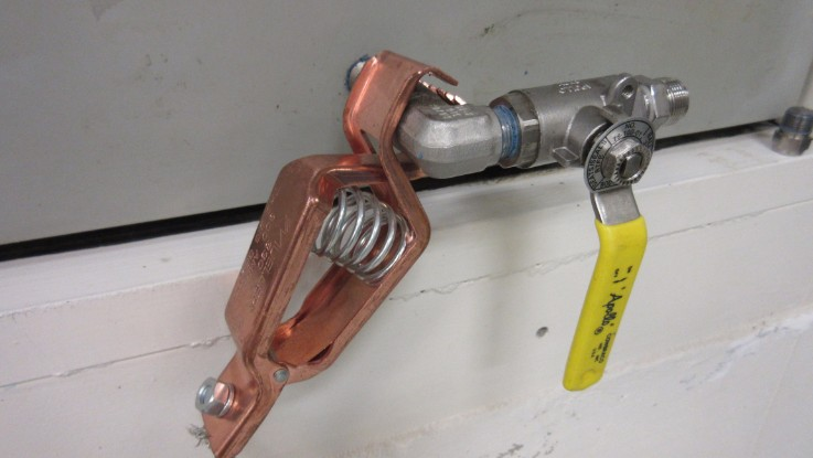
To drain the window a 1/2”polyethylene hose was attached to the drain line using a Swagelok fitting and routed into a 55 gallon drum. A vent valve on the expansion tank was opened to allow air to enter the window. It took approximately 5 hours to drain the window using this method. Approximately 50 US gallons were drained from the window, agreeing with the amount specified on Hot Cell Services drawing #96173-100 (attached).
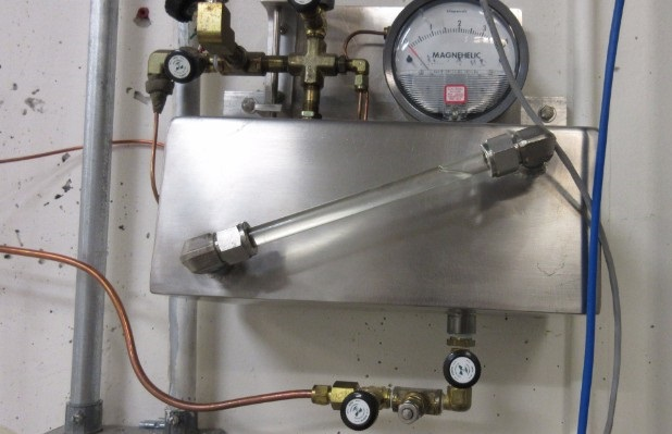
After draining, the window was purged with helium then pressurized to approximately 13” WC with helium. A pressure drop of 0.6” WC was observed over a 2 hour period. While pressurized, a Varian G8601-60001 leak detector was used to sniff for helium around the perimeter of the gaskets on both the hot and cold sides – no helium leaks detected. A small leak was found on the pressure gauge used to monitor helium pressure.
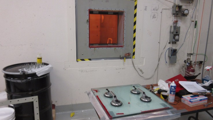
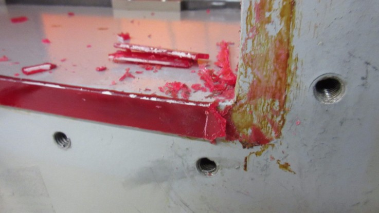
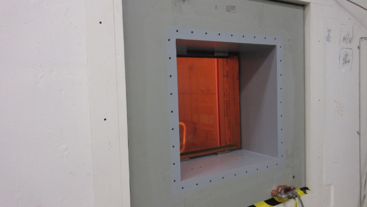
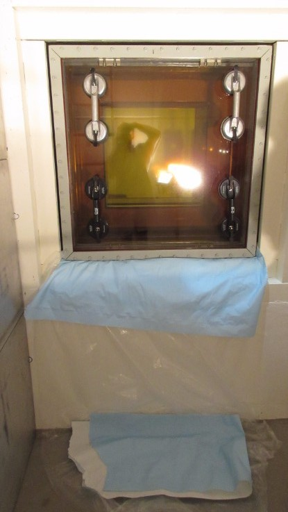
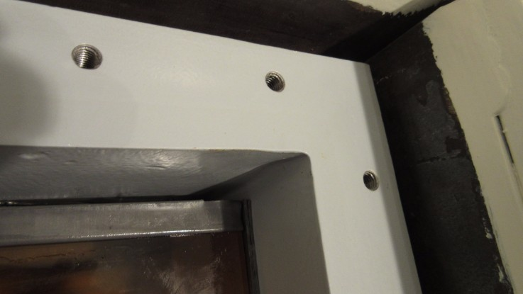
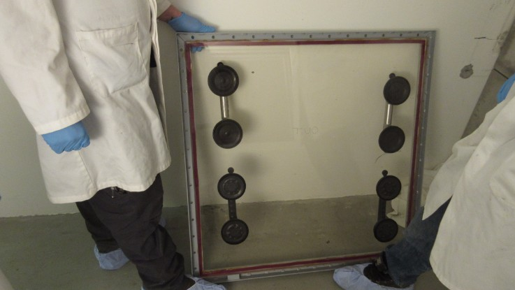
The cold side cover panel assembly was then removed following the HCS procedure. From HCS Drawing #96173-100, the weight of the cold side glass cover panel was estimated to be approximately 50lbs. The guide pins used were McMaster-Carr PN# 93460A385. The trim frame could be easily removed, however the glass panel was stuck to the window housing. A putty knife and isopropyl alcohol were used to cut through the gasket to separate the window from the housing. The alcohol did not damage the paint of the housing – acetone was also tested on a small area and did not cause damage to the paint. Two suction cup handles were used to transport the glass panel, and it was easily lifted by two people. Various methods were attempted to remove old gasket material and gasket adhesive from the trim frame and housing surfaces – the most successful was using a razor blade scraper to remove the majority of the material, followed by an acetone wipe to remove the remainder of the stuck-on gasket adhesive. The panel was reinstalled with new gaskets following the attached procedures - no issues encountered. After torqueing the trim frame bolts the window was leak checked as before. A drop of 0.8” WC was observed over two hours, and no helium could be detected around the perimeter of the new cold side gasket.
The hot side cover panel assembly was changed using the same method as for the cold side. The glass panel was estimated to be 150lbs. A small amount of oil (< 0.5 L) remained behind the hot side glass panel after draining which spilled out after removal of the glass. Four suction cup handles were used, and four people were required to remove and reinstall the panel. After installation the leak check was repeated with a drop of 0.3” WC observed over two hours, and no helium detectable around the perimeter of the hot side gasket.
The replacement gaskets were ordered from Hot Cell Services under PO# 3033973 matching the material and sizes specified on HCS drawing #96173-100.
The window was filled with Drakeol 10B LT MIN OIL NF, Product code: PEN1550-00-C-DR, PO #3034657. The window was filled by lifting the drum onto the walkway leading to the target hall entrance, and siphoning the oil out of the drum with a 1/2” polyethylene tube connected to the drain fitting, and an air vent open on the expansion tank. Oil was added until the expansion tank was approximately 80% full.
After filling was complete, the cold side housing was repainted using Macropoxy 646 epoxy paint, 4019 Flint Gray. When the inside of the NHC is next accessible the hot side trim frame bolts will be re-painted to protect the bare metal exposed from removing and reinstalling them.
Note that a quote for $74,313 ($56,823 USD) (PDF attached) was received from Hot Cell Services for them to do this job. We were able to successfully complete this ourselves with approximately $4500 required for the gaskets, $200 for other materials, and roughly 8 FTE days of work.

|
|
Friday, February 24, 2017, 15:12, Isaac Earle, North Hot-Cell, Development, , , NHC interior walls/floor/ceiling re-finished, sealed, and painted 8x
|
The North Hot Cell interior walls, floor, and ceiling were re-finished, sealed, and painted by Omni Coating from Feb 6 - 17 under PO #3036471. This job required 2-3 people for 4-6 hours per day over the 2 week period. First the existing surfaces were ground and/or sanded to remove existing coatings and protrusions/sharp edges. This was followed by a coat of primer to highlight uneven surfaces and improve adhesion of following fillers and coatings. Metal shims between the cell walls and roof were cut away where they protruded into the cell. Loose steel cylinders between SHC and NHC spaces were fixed in place using epoxy filler. Epoxy or polyurethane fillers were used to fill all gaps, cracks, holes, etc, as detailed below. Foam backer rod and polyurethane filler were used to seal all large wall-to-wall and ceiling-to-wall gaps. An approximate 2cm radius rounded corner was formed at all wall-to-wall and floor-to-wall corners using polyurethane sealant. The interior of the tool-port, personnel access hatch, as well as the north roof hatch were also re-finished with the same procedure. After all sealing and finishing work the surfaces were coated with "Mill White" Macropoxy 646 Fast Cure Epoxy Paint as per manufacturer instructions. Note: this paint is recommended by the manufacturer for nuclear applications and has been tested for decontaminability: 99% water wash; 95% overall as per ASTM D4256/ANSI N 5.12 as well as for radiation tolerance: Passed ASTM D4082 / ANSI 5.12 with a 525 micron thick coating.
The following products were used as described (data sheets attached):
Sanitile 120 Universal Acrylic Primer - 50-75 micron dry film thickness coat applied over all existing ceiling, walls, and floor surfaces after preparation by sanding
Sika Duochem 8107 Epoxy Paste - Used for filling voids and cracks in concrete surfaces
Sikaflex 291 Polyurethane Elastomeric Adhesive and Sealant - used for caulking joints and cracks in the concrete walls and aluminum panel wall and for creating radiused corners in wall-to-wall and wall-to-floor corners
Macropoxy 646 Fast Cure Epoxy Paint - 4 coats applied on all surfaces using rollers or brushes to create a total thickness of 525 microns as per data sheet

|
|
Tuesday, February 28, 2017, 17:51, Isaac Earle, North Hot-Cell, Development, , , NHC flanged ducting connection sealed
|
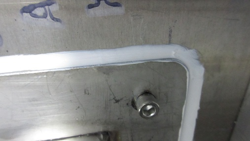
The North Hot Cell ducting (IRH1617) has been sealed with a bead of Sikaflex 1a polyurethane construction sealant where the flanged connection bolts to the NHC/TCS partition wall. When this sealant shows signs of aging it may be cut away and re-applied without unbolting the flange.
|
|
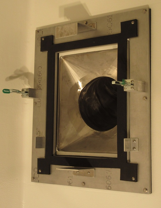
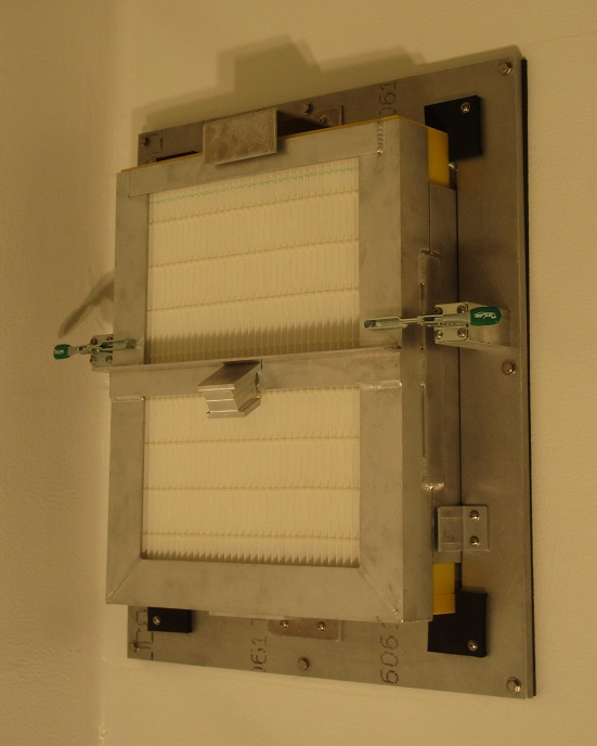
Thursday, March 02, 2017, 15:02, Isaac Earle, North Hot-Cell, Development, , , NHC roughing filter installed
|
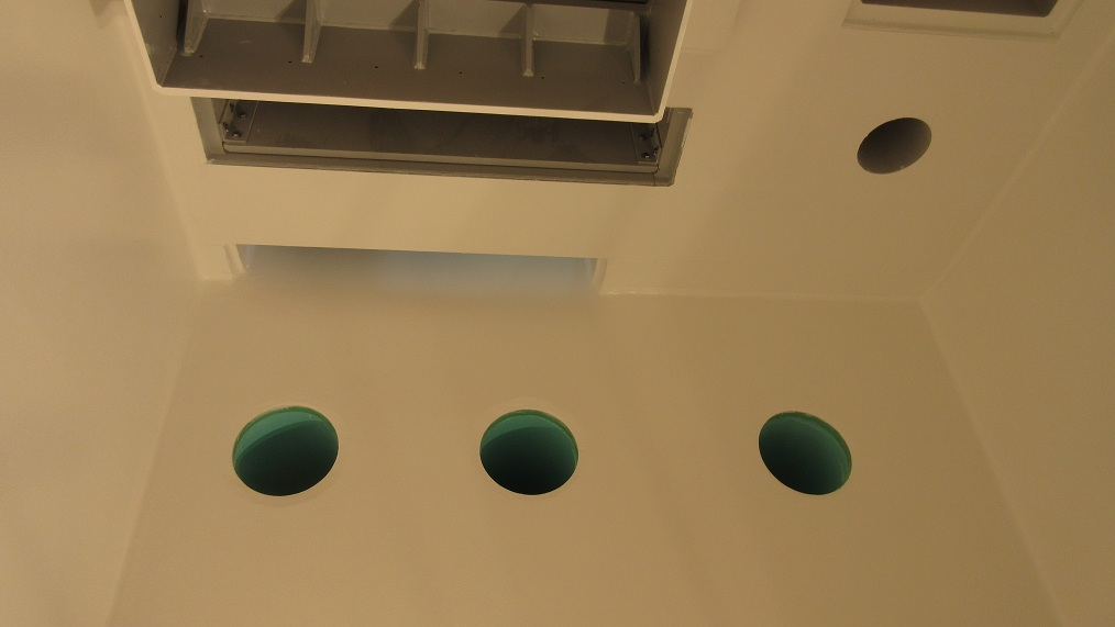
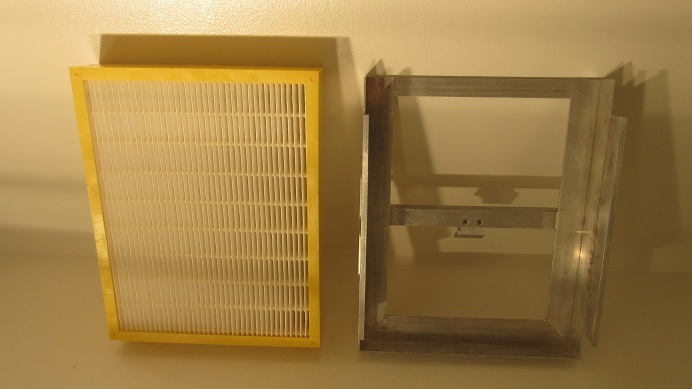
The roughing filter assembly (RFM0001D) has been installed at the ventilation exhaust hole on the NHC partition wall. The filter used is Model # 332-528-002 supplied by BGE Service & Supply Ltd (see PO # TR123998). Installation and removal of the filter using the manipulators will be tested after they have been installed.
|
|
Thursday, April 27, 2017, 16:58, Isaac Earle, North Hot-Cell, Development, , , Right side NHC manipulator installed
|
Installation of the NHC right side manipulator was completed yesterday. The three piece manipulator was assembled in the module assembly area on the manipulator cart which was then craned through the hatch to the NHC service area (the slave end had to be removed for it to fit through the hatch). The installation went relatively smoothly except for the second (cold side) piece of lead shielding around the thru tube which would not fit because the OD of the two halves were not concentric when assembled (arrived this way from CRL). The shielding was removed and 0.070" was cut down on the lathe, after which installation could be completed. The slave end lift bail and the pulley cover panel had to be removed for the manipulator to fit through the thru-tube. Both these items were reinstalled after the manipulator was in the wall, and it was confirmed that the slave end lift bail aligns with the slave-end removal hatch in the NHC roof. There was some difficulty getting the slave end to the horizontal position using the Y motion drive, also while preparing the manipulator for installation we noticed one of the Z motion tapes on the master side was sliding to the edge of one of the pulleys and rubbing - both these issues will be investigated at a later date.
We confirmed that it is possible to remove the master end using the manipulator cart. We will practice doing this at some point before the cell is commissioned. We will also do a run-through of slave end removal through the NHC roof.
Electronic copies of the Model-N installation and removal manual as well as the manipulator cart user manual are attached for future reference.
|
|
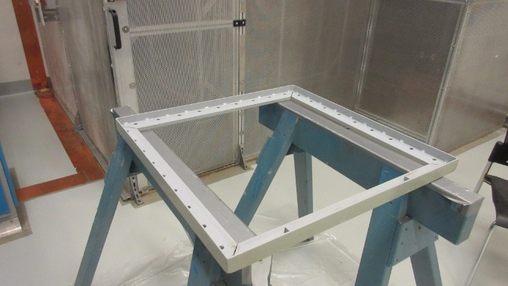
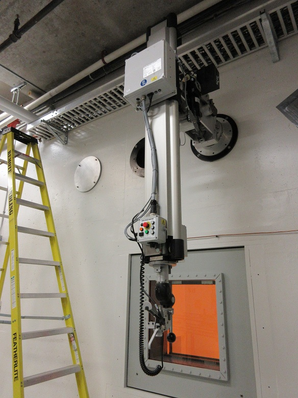
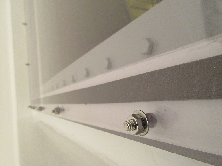
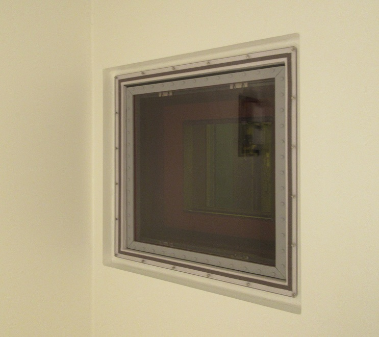
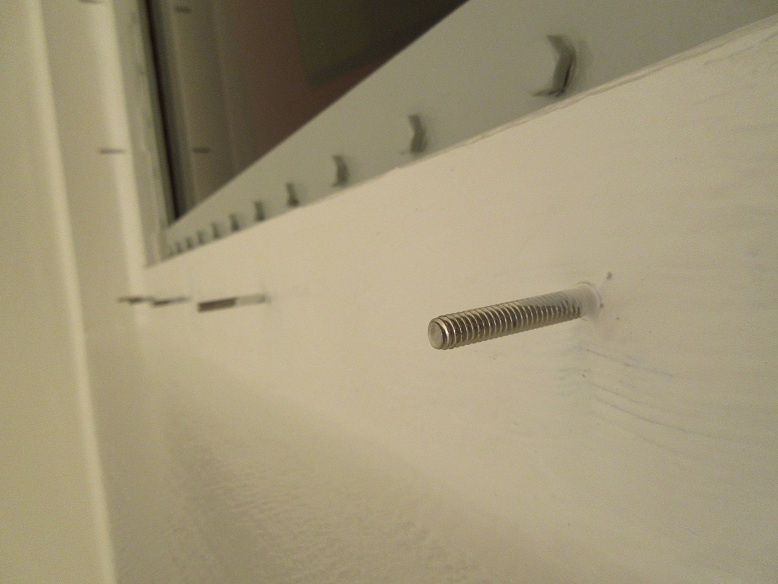
Tuesday, May 02, 2017, 09:48, Isaac Earle, North Hot-Cell, Development, , , NHC polycarbonate window cover panel installed
|
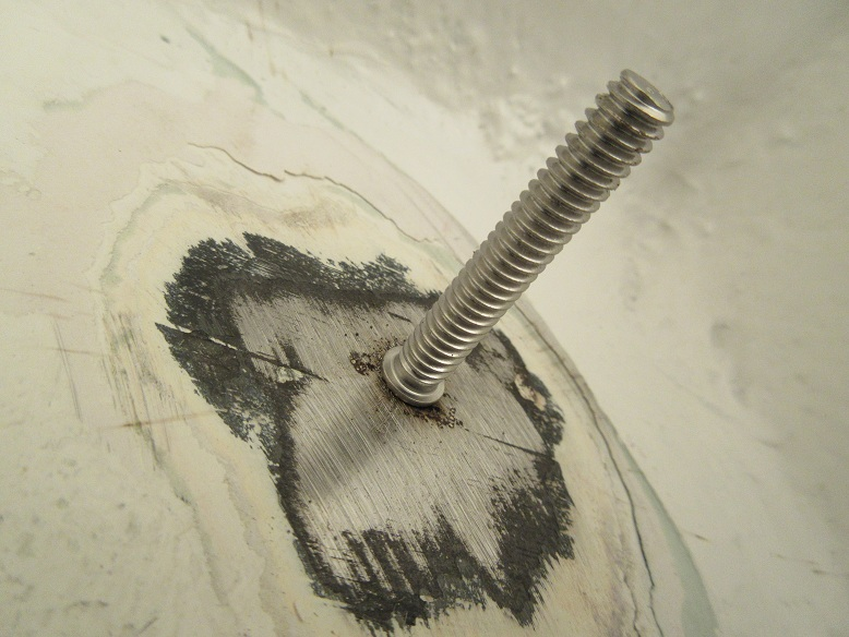
The window cover panel has been installed on the hot side of the NHC shielding window according to drawing IRH1638. It was necessary to drill and tap a hole in the steel frame first to achieve proper grounding for stud welding. The strength of all studs were checked by installing a nut on the stud tightened against a block up against the steel frame, which was then torqued to a minimum of 10 ft*lbs. For the final installation the nuts were each torqued to approximately 3 ft*lbs. Visibility from the cold side of the cell was checked before and after installation by Chad Fisher and Isaac Earle: no distortion was caused by the new cover panel and with the in-cell work lights aimed in a similar direction to how the permanent lights will be installed (shining down from the roof, and also aimed south from the periphery of the window) there was no significant decrease in visibility of the work space. A couple of small scratches are visible on the panel surface - these were already there when the panel arrived at TRIUMF. The panel has been installed in an orientation that will minimize the visibility of these scratches during normal work. When the work lights were aimed at the window many imperfections in the panel were visible, however this is not expected to occur during normal operation. After the cell lighting has been installed the visibility will be re-evaluated and a new panel can be procured if necessary.
|
|
Thursday, May 11, 2017, 16:10, Isaac Earle, North Hot-Cell, Development, , , NHC roof block to TH north wall gap sealed
|
The gap between the north face of the NHC roof block and the target hall north wall in the area where the NHC inlet ducting will be installed has been sealed with Sikaflex 1a flexible polyurethane sealant applied over foam backer-rod. |
|
Thursday, June 15, 2017, 11:29, Isaac Earle, North Hot-Cell, Development, , , NHC inlet ducting installed
|
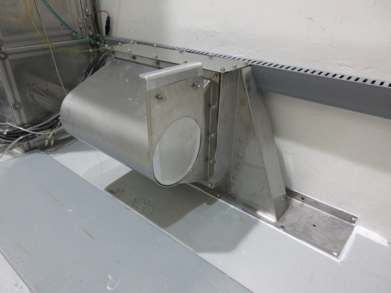
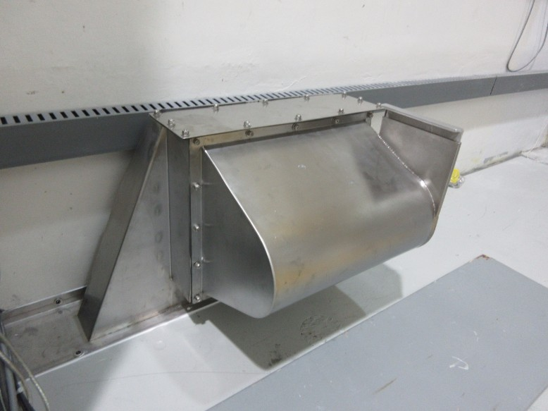
The North Hot Cell inlet ducting assembly was installed today in the target hall at the north end of the NHC roof block. A small section of the perforated aluminum sheet on the TCS cage had to be trimmed for the assembly to fit (see IMG_0214). At each end of the assembly it was fastened to the roof structure using a 1/4"-20 tapped hole in the steel roof, and a 1/4"-20 anchor in the north wall of the target hall. The base flange of the assembly was sealed to the roof structure and TH wall using Sikaflex 1A polyurethane sealant on all sides.
|
|
Friday, June 23, 2017, 17:28, Isaac Earle, North Hot-Cell, Development, , , NHC module flange and cameras installed
|
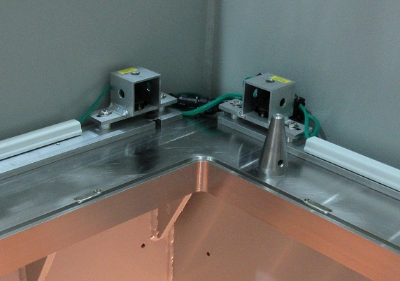
The North Hot Cell module support flange (IRH1152D) was installed on June 21, 2017 using 1/8" rubber sheet as a sealing gasket. The rubber was glued at the seams with Loctite 495 instant adhesive. Cameras with all required wiring and connectors were installed on the mounting bars (IGN0325D) and then aligned to provide the same view as at other module installation locations in the target hall. A cable with 5 video signals, and a camera power cable was routed from the south wall in the target hall (where video line connections are), to the panduit on the north wall. An additional section of cable will be installed to link to the flange cameras after cable covers are installed on the floor.
|
|
Wednesday, July 05, 2017, 15:36, Isaac Earle, North Hot-Cell, Development, , , NHC and SHC nuclear ventilation flow sensors installed
|
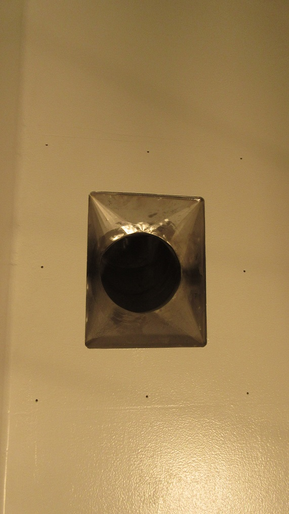
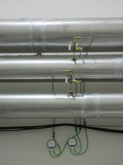
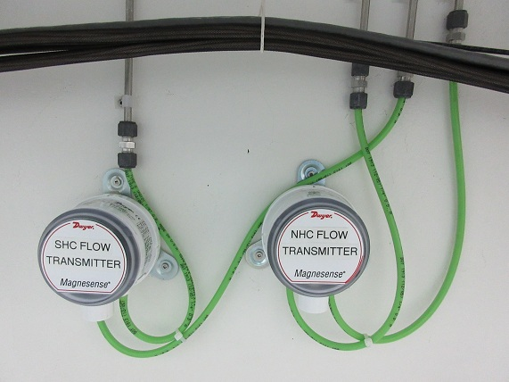
Installation of new flow sensors and transmitters for the NHC and SHC duct lines was completed in the target hall today. The sensors are Dwyer DS-300-8 in-line sensors for 8" pipe; The transmitters are Dwyer MS0121 magnesense differential transmitters with 4-20mA output. The transmitters will be wired to the new PLC control system when the upgrade is done.
|
|
Thursday, July 06, 2017, 14:23, Isaac Earle, North Hot-Cell, Repair, , , Slave side Z motion tape snapped on NHC right side manipulator
|
The NHC right side manipulator was evaluated today to check if operation was normal through all ranges of motion. The manipulator was first moved through usual motions without the electric motion drives: the feel was fairly normal, a sound could be heard from the master side Z motion tapes rubbing on the sides of the pulleys, this problem had been identified a few weeks ago however it was significantly reduced since the master side upper and lower Z motion tapes were tensioned yesterday (using CRL repair manual)
The Y motion drive was then tested: with the master arm close to the window we attempted to move the slave arm close to the slave side window using the Y motion drive; part way through travel the arm stopped moving and would not move any further towards the window. At this point it was approximately 1 foot from the slave side window. (I recall that when the manipulator was installed in the wall it was difficult to get the slave end fully horizontal, the arm would travel part way, then stop for seemingly no reason. Eventually after multiple attempts I got it to reach the horizontal position)
The Z motion was then tested. The slave end was moved to the fully extended position. At this point when the Z drive was continued downwards the master side moved up. Once it reached the upper limit the drive continued which caused the Z motion tape on the slave end to snap. At this point testing was stopped.
Our plan is to assemble and test the left side manipulator after the manipulator handling cart repair is completed. If the left side has the same problems it is likely a manufacturer defect. If not, the problems with the right side may be due to a timing error introduced when we removed the slave end to fit the assembly and cart through the roof hatch from the ISAC-1 experimental hall. In either case we plan to have CRL technician come in to address the issues and tune-up both arms before use. |
|
Wednesday, August 09, 2017, 16:39, Isaac Earle, North Hot-Cell, Development, , , NHC drain line into sump identified
|
The NHC drain line was tested by pouring approximately 10 gallons of water through the drain grate at the base of the NHC partition wall. Water was seen a few minutes later pouring into the sump labeled "ACTIVE SUMP" from the light coloured pipe on the west side of the inside of the sump. Rob Walker had previously said that the hot cells drain into the sump next to this one which is labeled "SANITARY SUMP", which appears to be incorrect. |
|
Tuesday, August 15, 2017, 12:10, Isaac Earle, North Hot-Cell, Development, , , ISAC Active Sump low water level measured
|
The ISAC active sump in the Active Service Room (#002 on B2 level) was pumped out yesterday using the standard procedure (Section 5.5.2 of the ISAC Operators' Manual, V1.0). The procedure makes use of the auto stop feature of the pump-out system which stops when a low level float switch is triggered. The water level was measured after pumping stopped, and was found to be approximately 21" above the base of the sump. A new section of pipe will be added to the 4" drain line in the sump to move the drain opening below the low level water line so that air in the sump is not pulled into the drain network (which could end up in the NHC or TCS space). |
|