| ID |
Date |
Author |
Category |
Type |
Module |
Target/Number |
Subject |
|
1800
|
Friday, October 05, 2018, 14:41 |
Travis Cave | Spent Target Vault | Standard Operation | | UC#24 | Spent Target Move |
UC#24 has been moved from the south hot cell to the spent target vault. The target is in pail #171 and placed in spot 4C. See attached PDF for details. |
| Attachment 1: Target_Index_2018-10-05.pdf
|


|
|
1799
|
Wednesday, October 03, 2018, 14:16 |
David Wang | South Hot-Cell | Standard Operation | TM4 | Ta #57 | Leak check TM4 Lp Ta# 57 at SHC. |
Tried to leak check TM4 Ta57# at TCS. LD failed to pump down properly at fine range. It always tripped at 4 torr. I cheeked all vacuum lines seals and adapters on top of module to LD. Everything is good. Chad said the VCRs at SHC can not be tightened any more. Discussed with Anders, we decide to move module TCS and helium pressure test there. The same difficult happened last time on TM4 UCx24# at SHC when leak check. But,it is solved by pressurize the line at SHC last time.
The HS line was pressurized with 70 psi helium on Oct 04th at TCS.. LD 0,00X E-9atm.cc/sec no change in 2 minutes. No leak. |
|
1798
|
Tuesday, October 02, 2018, 09:59 |
Travis Cave | South Hot-Cell | Standard Operation | TM4 | UC#24 | Module move |
TM#4 with UC#24 has been moved from the east target station to the south hot cell. |
|
1797
|
Tuesday, October 02, 2018, 09:49 |
David Wang | ITE | Standard Operation | TM4 | UCx 24# | TM4 was disconnected in ITE. |
TM4 was disconnected in ITE yesterday. See attachment for checklist. |
| Attachment 1: TM2_UCx_24#_disconnection_in_ITE..pdf
|


|
|
1796
|
Thursday, September 27, 2018, 13:58 |
Travis Cave | Conditioning Station | Standard Operation | TM3 | no target | Module move |
TM#3 has been moved from the conditioning station to the centre east silo. This will be its new home after the silo switcher-roo. |
|
1795
|
Wednesday, September 26, 2018, 07:14 |
David Wang | Conditioning Station | Repair | TM3 | | TM3 HV test at TCS. |
I did a HV test on TM3 at TCS yesterday. HV Ramp up speed: 1KV per 5 minutes when below 30KV,1KV per 10 minutes from 30-36KV. There is no major spark below36 KV . I could see lots small and big vacuum response on IG1 and PNG2 when conditioning from 30-36 KV, especially when closing to 36 KV. However, At 36.4 KV, There is a big continuous spark occurred. It could not be stopped until I lowed the HV to 14KV. I have to ramp up from 14 KV again. This behavior on TM3 HV test is same as before we saw. The module can not pass 36KV at present condition. During the test., EL is tied to 60KV bias. The HV cover on TM3 top is installed. And, Service tray cover plate is installed on TM3. |
|
1794
|
Tuesday, September 25, 2018, 08:48 |
chad fisher | South Hot-Cell | Maintenance | | | Window leak and torque |
The south hot cell window has been found to be leaking oil. Upon inspection yesterday I found that the bolts compressing the gasket on the cold side were "loose". I have re-torqued them to the specification provided by the manufacturer in the attached procedure. |
| Attachment 1: hot_cell_window_gasket_change_procedure.pdf
|


|
|
1793
|
Tuesday, September 25, 2018, 08:01 |
chad fisher | South Hot-Cell | Standard Operation | TM2 | nSiC#1 | nSiC#1 install |
On September 18th installation of nSiC#1 was attempted on TM2. As usual, new fasteners were tested previous to insertion into hot cell and employed during installation. the last fastener to be installed was for the circuit D block. The fastener/air ratchet stalled immediately indicating a problem. The fastener was removed and a an attempt was made trying a new spare fastener. That fastener also jammed right away but could not be removed or installed any further.
A breaker bar was employed to achieve more torque and the fastener was able to be loosened, although it would not come completely out, dangling and wobbling like it was free. A claw type bar was used to add slight pressure to the fastener while it was loosened allowing the fastener to undo the rest of the way.
Target was removed and discovered that that insulator supporting circuit c and d blocks was quite broken and that a few chunks had fallen off. It was also notice that boefore the breaker bar had been employed that a piece of ceramic was on the table suggesting that the ceramic had been at least partially broken at the time of removal of the previous target. Also, the threads of the insert for circuit d showed damage an swarf.
Swarf was vacuum claned out of the circuit d thread insert and a machine tap ran through the insert twice.
nSiC#1 was reinstalled with new waterline gaskets and new c and d circuit fasteners with a little bit of the first 2-3 threads lightly coated with vacuum grease.
High current fasteners torqued to 130 in lbs. |
| Attachment 1: 20180919_132304.jpg
|

|
| Attachment 2: 20180919_143535.jpg
|

|
|
1792
|
Tuesday, September 25, 2018, 07:54 |
David Wang | Conditioning Station | Repair | TM3 | | TM3 is connected for HV test at TCS. |
water loops are by passed on top. All bias, EE, and EL are tied together. Started water system. |
|
1791
|
Monday, September 24, 2018, 14:50 |
Travis Cave | Spent Target Vault | Standard Operation | | UC#23 | Spent Target Move |
The spent UC#23 target has been moved from the south hot cell to the spent target storage. It was placed in pail #170 and place in spot #4B in the vault. |
|
1790
|
Monday, September 24, 2018, 10:21 |
Anders Mjos | South Hot-Cell | Standard Operation | TM2 | UC#23 | Post Irradiation Examination (PIE) |
UC#23 experienced short between target and heat shield as it was heated during operation. The inspection of the target after irradiation revealed that the left target leg was close to the heat shield opening and likely the cause of the short. Marks could be seen on the leg indicating contact. See attached photo. More photos are available on DocuShare |
| Attachment 1: 20180924_161322929_iOS.jpg
|

|
|
1789
|
Friday, September 21, 2018, 10:07 |
David Wang | ITW | Standard Operation | TM2 | SiC nano | TM2 with SiC nano target was has been connected in ITW. |
Tm2 with SiC nano has been connected in ITW. See attachment for checklist |
| Attachment 1: TM2_with_SiC_nano_connection_in_ITW..pdf
|


|
|
1788
|
Friday, September 21, 2018, 10:06 |
David Wang | ITW | Standard Operation | TM2 | UCx23 | TM2 was disconnected in ITW. |
TM2 was disconnected in ITW this Tuesday. See attachment for checklist. |
| Attachment 1: TM2_UCx_23#_disconnection_in_ITW..pdf
|


|
|
1787
|
Thursday, September 20, 2018, 14:36 |
Travis Cave | ITW | Standard Operation | TM2 | nSiC#1 | Module move |
TM#2 with nSiC#1 has been moved from the south hot cell to the west target station. |
|
1786
|
Thursday, September 20, 2018, 14:35 |
Travis Cave | South Hot-Cell | Standard Operation | TM2 | nSiC#1 | Electrical Check |
TM#2 with the nSiC#1 target had its check done on it at the south hot cell see attached for results. |
| Attachment 1: Electrical_Chk_TM2_SHC_nSiC#1_Sept-20-2018.pdf
|

|
|
1785
|
Thursday, September 20, 2018, 08:36 |
Travis Cave | South Hot-Cell | Standard Operation | TM2 | no target | Electrical Check |
Results of the electrical check on TM#2 with no target after Chad cleaned out the bolt hole on the module where the target mounts. |
| Attachment 1: Electrical_Chk_TM2_no_tgt_Sept-20-2018.pdf
|

|
|
1784
|
Tuesday, September 18, 2018, 12:59 |
Travis Cave | South Hot-Cell | Standard Operation | TM2 | UC#23 | Module move |
TM#2 with UC#23 has been moved from ITW to the south hot cell. The shield plug was also installed remotely as well. |
|
1783
|
Friday, September 14, 2018, 09:39 |
Travis Cave | Conditioning Station | Standard Operation | TM3 | no target | Module move |
TM#3 with no target has been moved from the north east silo to the conditioning station. |
|
1782
|
Thursday, September 13, 2018, 16:57 |
Isaac Earle | North Hot-Cell | Development | | | NHC grounding and mili-ohm testing |
The following equipment has been connected to the building ground located in the Target Hall by the TCS using 1/2" flat bonding strap:
- NHC roof structure
- NHC/TCS partition wall
- NHC work table
The following equipment has been connected to the building ground by connecting to the work table inside the NHC using 1/2" flat bonding strap:
- Air and gas supply line mounting bracket inside NHC
- Receptacle box mounting bracket inside NHC
- Diagnostic signal box mounting bracket inside NHC
The resistance between the following locations and the copper grounding plate located at the base of the NHCSA north wall were measured. The resistance of the wire used was 258.10mΩ, and has been subtracted from the following results.
Measurements taken in NHCSA:
- Control panel below viewing window (base plate of box): 4.67mΩ
- Oil window frame (bare metal drain valve): 55.34mΩ
- Left manipulator (ground plate near e-stop button): 73.46mΩ
- Right manipulator (ground plate near e-stop button): 202.58mΩ
- Air and gas supply line mounting bracket: 40.68mΩ
- Diagnostic connector box: 12.15mΩ
- Steel conduit for 110V supply to hot cell interior: 4.81mΩ
Measurements taken inside NHC:
- Work table: 4.51mΩ
- Pre-filter bolted to partition wall: 4.84mΩ
- Table hatch lid: open load
- Left manipulator thru tube: 515.8mΩ
- Right manipulator thru tube: 342.0mΩ
- Left manipulator (slave boot plate bolt): 885.9mΩ
- Right manipulator (slave boot plate bolt): 1444.0mΩ
- Grounding strap for air/gas plate: 4.84mΩ
- Outside of SHV connector on diagnostic signal box: 4.56mΩ
- Exterior of 110V electrical conduit: 3.88mΩ
- Male Staubli connector for 1st gas line: 53.7mΩ
- Welded stud for window cover panel: 6.06mΩ
- Grounding strap for partition wall: 4.39mΩ
- Roof structure (measured inside un-painted bolt hole): ~0mΩ
- Stainless steel module flange: ~0mΩ
Dedicated grounding will be added in the near future for the oil window frame and the manipulator thru-tubes. Testing will then be repeated for those items.
Dec 18, 2018 update:
The oil window frame and both manipulators (where they bolt to the thru-tubes) were connected to the building ground using 1/2" flat bonding strap connected at the cold side of each piece of equipment, and running to the grounded copper sheet located in the NHC service area at floor level. The connection is made inside the electrical racks located directly west of the NHC operator area on the cold side. This work was done by Travis Cave in October 2018.
Mili-ohm testing for these items has not yet been repeated.
Jan 14, 2019 update:
Grounding was added from the metal plate near the e-stop button on the master arm of both manipulators. The same 1/2" flat bonding strap was used which was tied into other bonding strap which runns to the grounded copper sheet in the NHCSA.
Mili-ohm testing was repeated for the following items:
- Oil window frame (bare metal drain valve): 13.6mΩ
- Left manipulator (ground plate near e-stop button): 16.1mΩ
- Right manipulator (ground plate near e-stop button): 16.5mΩ
|
|
1781
|
Wednesday, September 12, 2018, 15:30 |
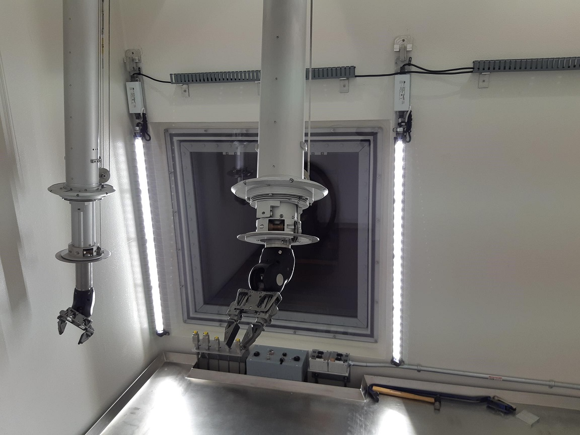
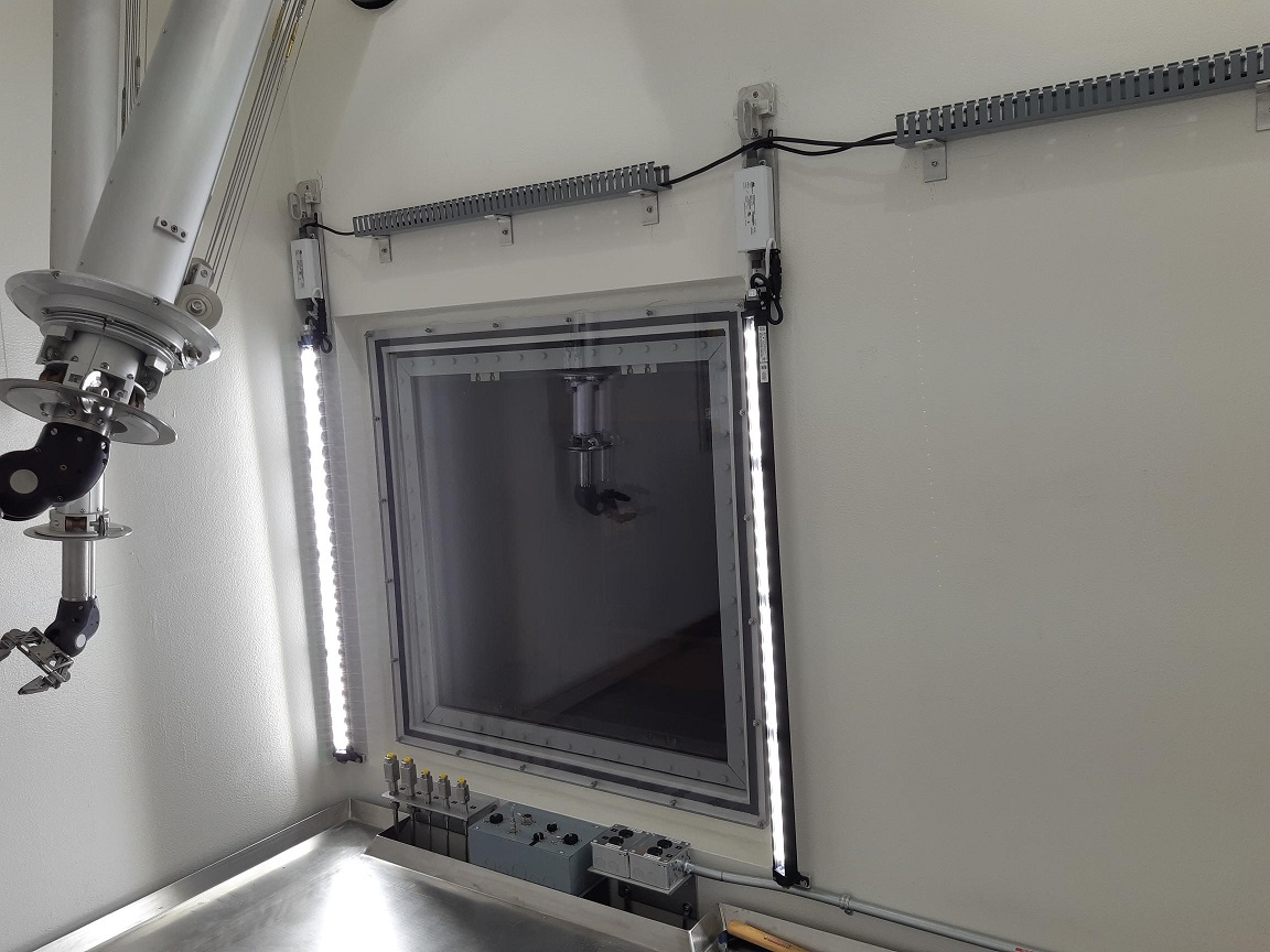
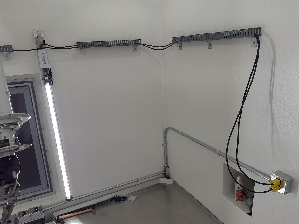
Isaac Earle | North Hot-Cell | Development | | | Installation of NHC operator-level lighting completed |
Installation of of operator-level lighting in the NHC was completed today according to drawing IRH1801. 2" x 2" Panduit was mounted to the wall on aluminum brackets to support the power cables. These lights can be replaced remotely by unplugging the power cords using the manipulators, lifting the cable out of the Panduit with a hooked pole tool through the manipulator slave end removal roof hatch, lifting the light fixture off the support bracket with the pole tool, then installing a new fixture in the opposite order. This RH procedure will be tested at a later date as part of NHC commissioning.
|