| ID |
Date |
Author |
Category |
Type |
Module |
Target/Number |
Subject |
|
1564
|
Friday, June 23, 2017, 17:28 |
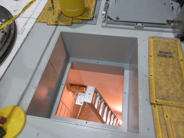
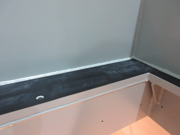
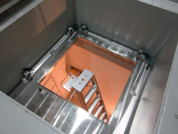
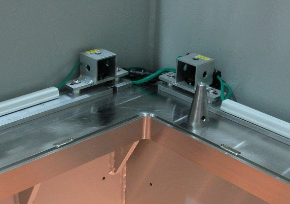
Isaac Earle | North Hot-Cell | Development | | | NHC module flange and cameras installed |
The North Hot Cell module support flange (IRH1152D) was installed on June 21, 2017 using 1/8" rubber sheet as a sealing gasket. The rubber was glued at the seams with Loctite 495 instant adhesive. Cameras with all required wiring and connectors were installed on the mounting bars (IGN0325D) and then aligned to provide the same view as at other module installation locations in the target hall. A cable with 5 video signals, and a camera power cable was routed from the south wall in the target hall (where video line connections are), to the panduit on the north wall. An additional section of cable will be installed to link to the flange cameras after cable covers are installed on the floor.
|
| Attachment 3: IMG_0240.jpg
|

|
|
1574
|
Thursday, June 29, 2017, 11:55 |
David Wang | Conditioning Station | Repair | | | TCS HV cable and feed through installation |
John Chow and I installed new TCS HV cable and feed through with their mounting panel back to TCS Faraday cage this Tuesday. ECO-4269 has been issued for the new cable feed through and mounting panel. |
|
1575
|
Thursday, June 29, 2017, 14:42 |
Travis Cave | Spent Target Vault | Standard Operation | | UC#20 | Spent Target Move |
The spent UC#20 has been moved from the south hot cell to the spent target vault. It was placed in pail #150 and spot 1B in the vault. See attached for details of the vault. |
| Attachment 1: Vault_Storage_June_29_2017.pdf
|


|
|
1577
|
Wednesday, July 05, 2017, 15:36 |
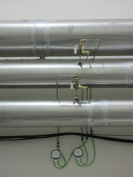
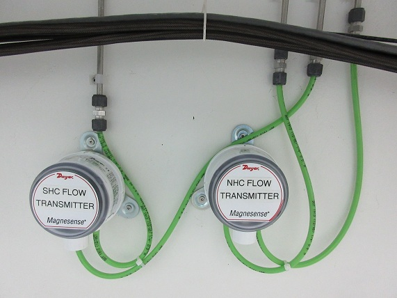
Isaac Earle | North Hot-Cell | Development | | | NHC and SHC nuclear ventilation flow sensors installed |
Installation of new flow sensors and transmitters for the NHC and SHC duct lines was completed in the target hall today. The sensors are Dwyer DS-300-8 in-line sensors for 8" pipe; The transmitters are Dwyer MS0121 magnesense differential transmitters with 4-20mA output. The transmitters will be wired to the new PLC control system when the upgrade is done.
|
|
1578
|
Thursday, July 06, 2017, 14:23 |
Isaac Earle | North Hot-Cell | Repair | | | Slave side Z motion tape snapped on NHC right side manipulator |
The NHC right side manipulator was evaluated today to check if operation was normal through all ranges of motion. The manipulator was first moved through usual motions without the electric motion drives: the feel was fairly normal, a sound could be heard from the master side Z motion tapes rubbing on the sides of the pulleys, this problem had been identified a few weeks ago however it was significantly reduced since the master side upper and lower Z motion tapes were tensioned yesterday (using CRL repair manual)
The Y motion drive was then tested: with the master arm close to the window we attempted to move the slave arm close to the slave side window using the Y motion drive; part way through travel the arm stopped moving and would not move any further towards the window. At this point it was approximately 1 foot from the slave side window. (I recall that when the manipulator was installed in the wall it was difficult to get the slave end fully horizontal, the arm would travel part way, then stop for seemingly no reason. Eventually after multiple attempts I got it to reach the horizontal position)
The Z motion was then tested. The slave end was moved to the fully extended position. At this point when the Z drive was continued downwards the master side moved up. Once it reached the upper limit the drive continued which caused the Z motion tape on the slave end to snap. At this point testing was stopped.
Our plan is to assemble and test the left side manipulator after the manipulator handling cart repair is completed. If the left side has the same problems it is likely a manufacturer defect. If not, the problems with the right side may be due to a timing error introduced when we removed the slave end to fit the assembly and cart through the roof hatch from the ISAC-1 experimental hall. In either case we plan to have CRL technician come in to address the issues and tune-up both arms before use. |
|
1579
|
Monday, July 10, 2017, 09:09 |
Dan McDonald | North Hot-Cell | Repair | | | manipulator cart repair |
A hydraulic leak was found on the manipulator install and repair cart, upon further investigation the cause was a faulty cylinder. Once the cylinder was removed and disassembled the inner bore was found to be scored beyond repair. Another point of interest was that the rod was painted to the point that when retracted it compromised the rod seal causing the cylinder to leak. attached are photos outlining the issues. new cylinders are being sourced and will be installed upon arrival. We have found that there is interaction between the tops of the cylinders and the bed of the cart when fully retracted and compressed, this might require some modifications to ensure proper operation in the future.
|
| Attachment 1: IMG_2955.JPG
|

|
|
1582
|
Wednesday, July 12, 2017, 11:05 |
Anders Mjos | Conditioning Station | Maintenance | | | Testing of new high voltage cable |
The target hall has been locked-out as per Document-70039.
Forced IG1, IG1S and IG2 to switch on BIAS power supply
Wednesday, July 12, 2017, 11:53: 70 kV at 0.16 mA
2 sparks observed shortly after 70 kV was reached
Wednesday, July 12, 2017, 12:59: No sparks for the last hour.
BIAS power supply off. Forces removed. |
| Attachment 1: 2017-07-12_HV_Cable_Test.xlsx
|
|
1586
|
Tuesday, July 18, 2017, 15:04 |
Travis Cave | Crane | Maintenance | | | Failure of the ISAC TH Crane Rotate. |
Earlier in the day it was noted that the rotate function of the crane had creased operation. After David has finished the block moves. Don and I checked the Crane's control unit in the ISAC crane control room and found the breaker tripped for the rotation. The breaker was reset and the crane's rotation is now operational. If this occurs in the future only Travis Cave, Don Jackson or a TRIUMF Electrician are allowed in that control box as it is a 480Volt system. Don or I because we know what we are looking for and the Electrician because they are allowed to touch with and deal 480 V systems. |
|
1592
|
Wednesday, August 02, 2017, 15:41 |
Keith C Ng | Assembly/Bench Test | Development | | | spare source tray build |
After re zeroing alignment telescope to master jig and adjusted parts into place:
Orientation: X = Left -, Right+; Y = Up +, Down -
Front wire target
X = 0.000, Y = 0.000
Rear wire target
X = 0.000, Y = +.008" (high)
All fasteners torqued to specification, steerer housing and assembly not installed yet. Weight of steerer assembly might cause rear to sag into place. Otherwise may attempt to split difference between the front and rear elements (alignment is on an angle in the horizontal vertical plane.) |
| Attachment 1: 20170802_sourcetray_RHB_8264.JPG
|

|
| Attachment 2: 20170802_sourcetray_RHB_8266.JPG
|

|
|
1593
|
Thursday, August 03, 2017, 15:02 |
Travis Cave | Spent Target Vault | Standard Operation | | SiC#36 | Spent Target Move |
The spent SiC#36 has been moved from the south hot cell to the spent target vault. |
| Attachment 1: Vault_Storage_August_3_2017.pdf
|


|
|
1596
|
Wednesday, August 09, 2017, 16:39 |
Isaac Earle | North Hot-Cell | Development | | | NHC drain line into sump identified |
The NHC drain line was tested by pouring approximately 10 gallons of water through the drain grate at the base of the NHC partition wall. Water was seen a few minutes later pouring into the sump labeled "ACTIVE SUMP" from the light coloured pipe on the west side of the inside of the sump. Rob Walker had previously said that the hot cells drain into the sump next to this one which is labeled "SANITARY SUMP", which appears to be incorrect. |
|
1599
|
Tuesday, August 15, 2017, 12:10 |
Isaac Earle | North Hot-Cell | Development | | | ISAC Active Sump low water level measured |
The ISAC active sump in the Active Service Room (#002 on B2 level) was pumped out yesterday using the standard procedure (Section 5.5.2 of the ISAC Operators' Manual, V1.0). The procedure makes use of the auto stop feature of the pump-out system which stops when a low level float switch is triggered. The water level was measured after pumping stopped, and was found to be approximately 21" above the base of the sump. A new section of pipe will be added to the 4" drain line in the sump to move the drain opening below the low level water line so that air in the sump is not pulled into the drain network (which could end up in the NHC or TCS space). |
|
1600
|
Thursday, August 17, 2017, 14:38 |
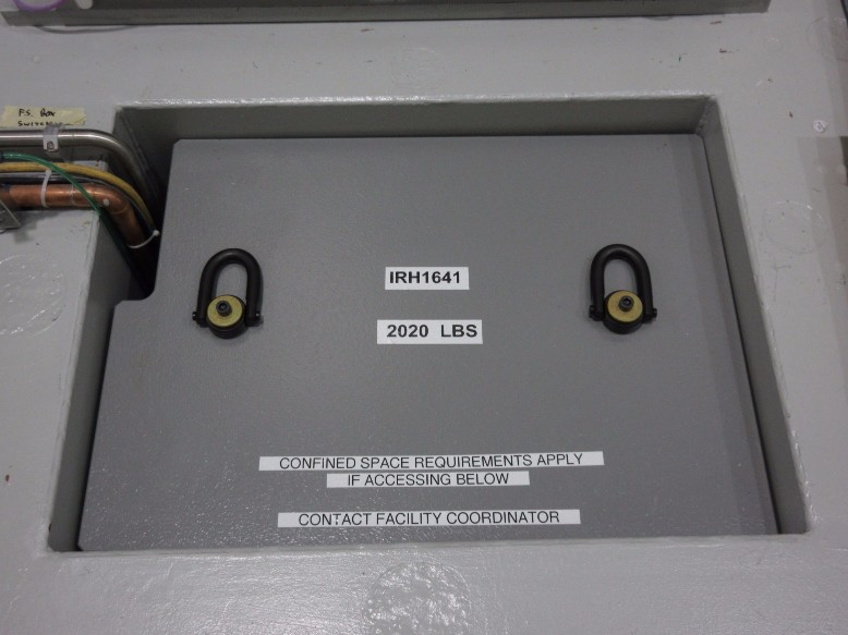
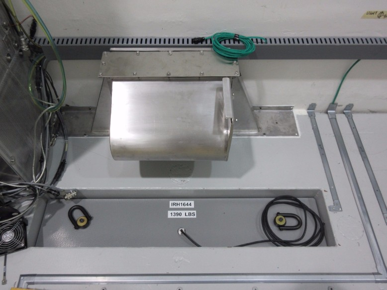
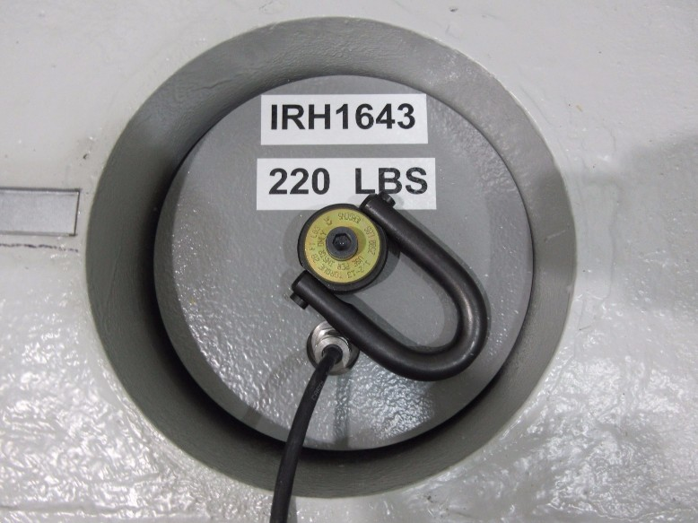
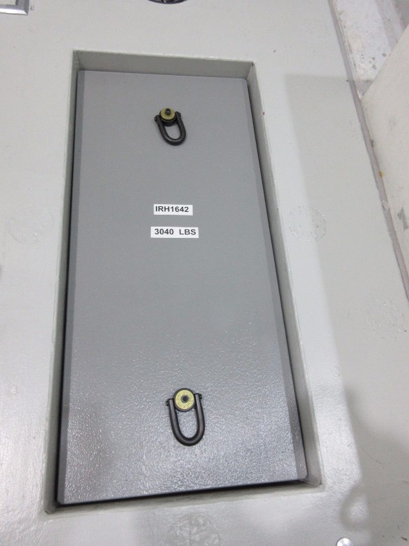
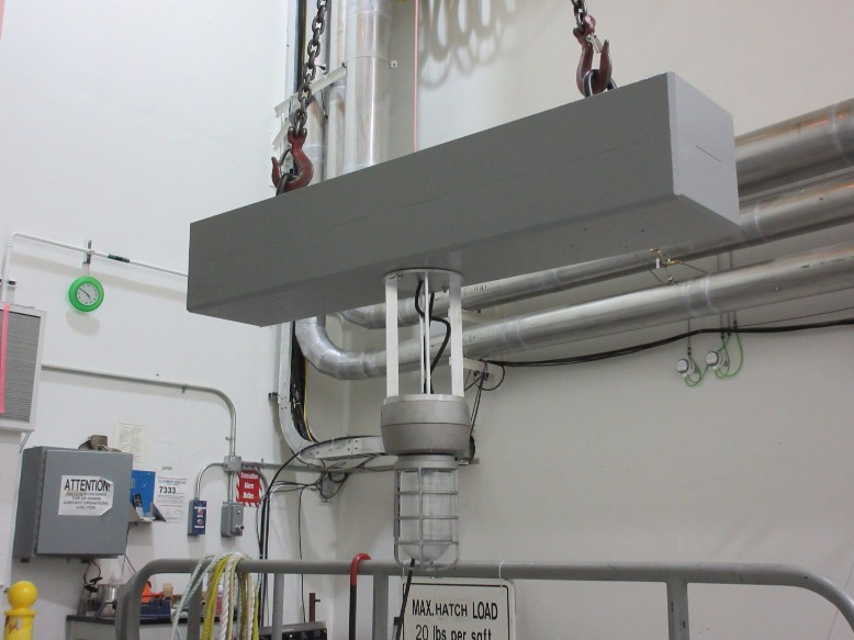
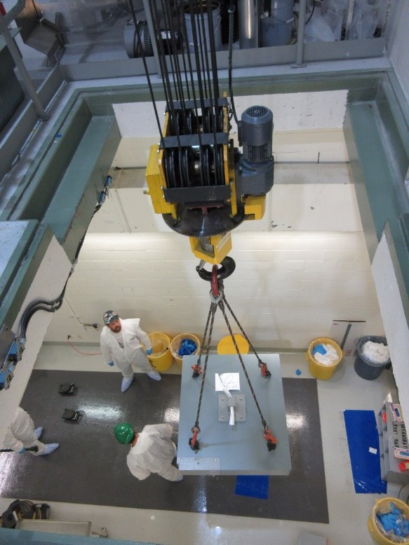
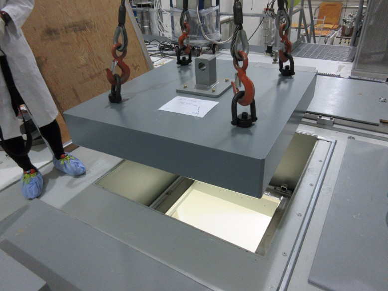
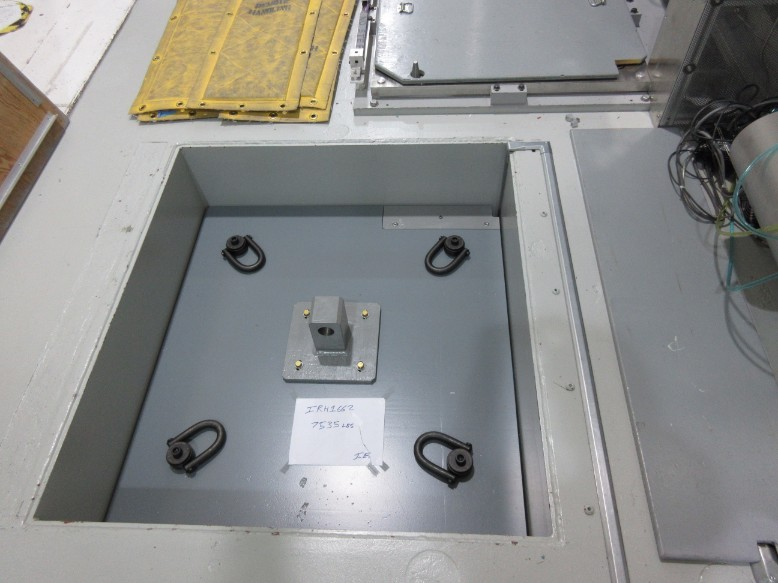
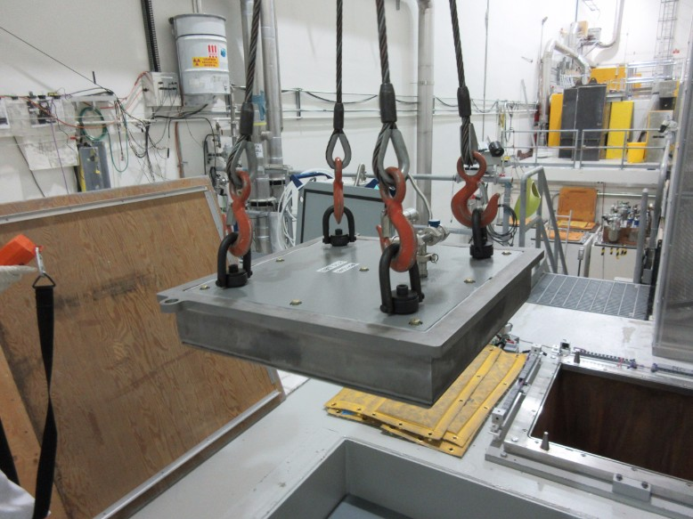
Isaac Earle | North Hot-Cell | Development | | | 4/6 NHC roof blocks installed |
Roof blocks IRH1641, IRH1642, IRH1643, and IRH1644 have been fully assembled, labeled, and installed as per drawing IRH1652. Fabrication of TCS shield block (IRH1646) and NHC module port block (IRH1645) is still in progress.
|
| Attachment 1: IMG_0381.jpg
|

|
|
1601
|
Friday, August 25, 2017, 16:33 |
Anders Mjos | Conditioning Station | Repair | | | Testing HV after cooling line repair |
The BIAS voltage was brought up to 70 kV today and held there for 1h. No sparking observed. |
| Attachment 1: 2017-08-25_HV_Water_Line_Test.xlsx
|
|
1608
|
Wednesday, August 30, 2017, 11:37 |
Travis Cave | Spent Target Vault | Standard Operation | | Ta#52 | Spent Target move |
The spent Ta#52 target has been moved from the south hot cell to the spent target vault. See attached PDF for details. |
| Attachment 1: Vault_Storage_August_30_2017.pdf
|


|
|
1617
|
Tuesday, September 19, 2017, 10:40 |
chad fisher | South Hot-Cell | Maintenance | | | South East Manipulator Maintenence |
Entered hot cell to preform replacement of slave tong cable. Existing cable shows no signs of wear so it has been re-installed. A spare tong cable has been loaded into a spare tong while in the hot cell in preparation for next time this cable needs to be replaced. |
|
1630
|
Thursday, September 28, 2017, 11:59 |
Travis Cave | Spent Target Vault | Standard Operation | | Ta#53 | Spent Target move |
The spent Ta#53 has been moved to the spent target vault. See attached file for details. |
| Attachment 1: Vault_Storage_September_28_2017.pdf
|


|
|
1634
|
Thursday, October 05, 2017, 11:04 |
Anders Mjos | ITW | Maintenance | | | Installation of new valve for module move ventilation |
David installed the new ball valve and connections for the SAS project module move ventilation. SASP0482. Drawing reference ISK5029B. |
|
1635
|
Friday, October 06, 2017, 11:12 |
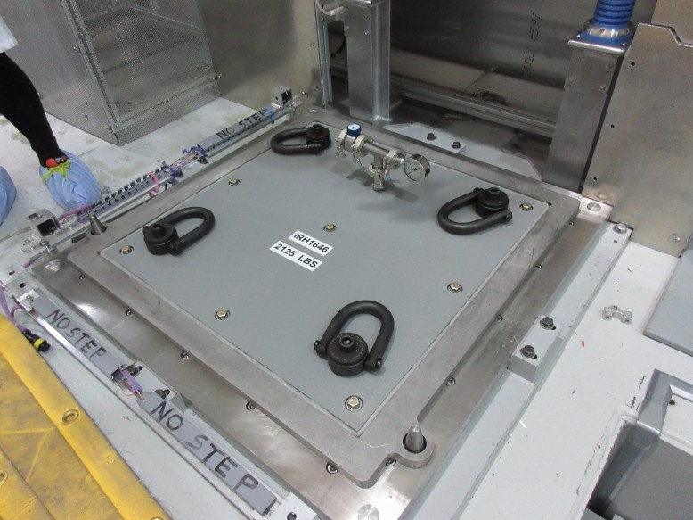
Isaac Earle | North Hot-Cell | Development | | | NHC module port shield block and TCS vessel shield block installed |
The NHC module port shield block (IRH1645) and the TCS vessel shield block (IRH1646) were installed yesterday in the target hall according to assembly drawing IRH1652. No issues were encountered during installation. Vacuum was pulled on the TCS and a leak check was performed on the shield: no leaks found.
|
|
1636
|
Friday, October 06, 2017, 11:21 |
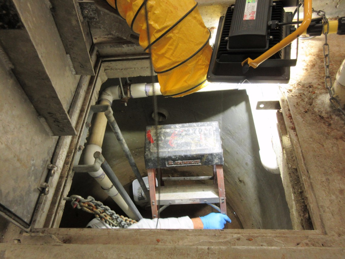
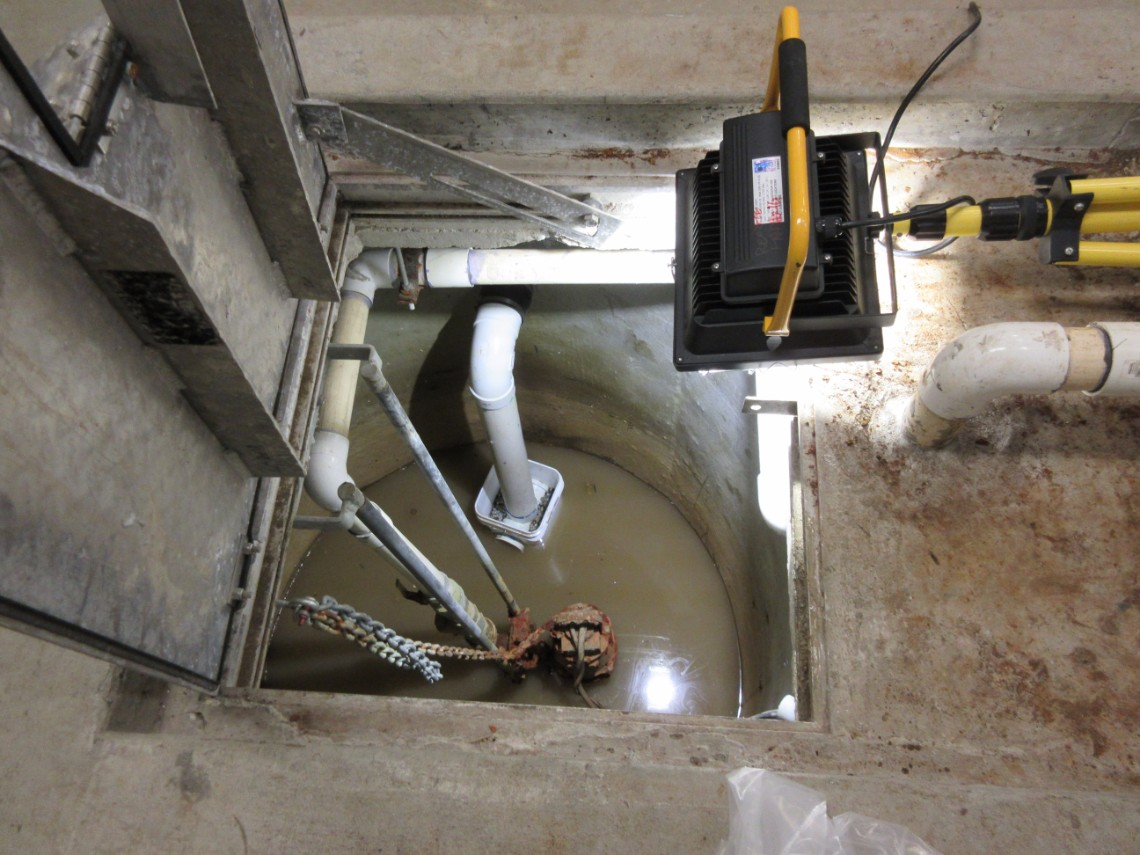
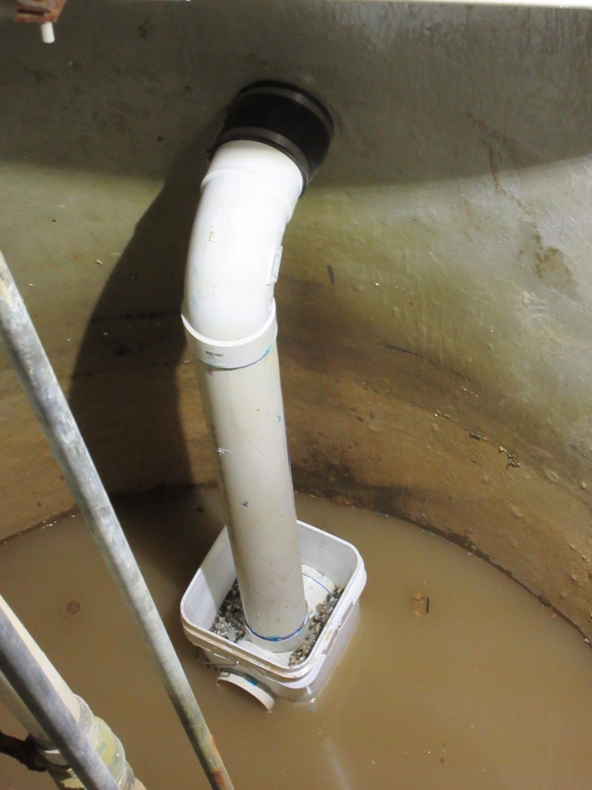
Isaac Earle | North Hot-Cell | Development | | | ISAC-1 active sump drain pipe modified |
The 4" PVC drain line in the ISAC-1 active sump was modified so that the drain pipe terminates below the low level water line of the automatic pump-out system. This will prevent backflow of sump gasses into the SHC, NHC, or TCS space if the air pressure in any of those rooms are lower than the sump air pressure. The details of the modification were specified by Mechanical Services Group, and the work was done by Paul Jensen. This system is defined in drawing IAM19183.
|