| ID |
Date |
Author |
Category |
Type |
Specific |
Subject |
|
343
|
Thursday, February 01, 2024, 11:16 |
Albert Kong | Standard Operation | Other | Cooling | Spent resin can rinse, purge, and drying |
The recently removed resin can from the T2 target station was rinsed with city water and flushed with compressed air for 1 cycle.
We will run it through a few more cycles before proceeding with drying under the fume extractor, at which point this ELOG will be updated.
UPDATE (Feb 08, 2024): The T2 resin can underwent 3 more air cycles. Today it was moved under the fume extractor with the lid cracked open and will be left to dry till next shutdown. It is worth noting that some clumps of old resin was found in the secondary resin can which was previously under the fume extractor. This resin should be disposed of alongside the T2 can's resin once dried.
|
|
347
|
Tuesday, May 07, 2024, 13:21 |
Albert Kong | Repair | Target 2 | Cooling | T2 Cooling System Expansion Tank Ultrasonic Level Sensor Repair |
At ~8am on May 06, the expansion tank level sensor for the T2 cooling system suddenly became noisy.
Cyclotron fault ref: 16915
Approximately 11:00 am today, the noisy sensor was replaced with a spare, upon which it was learned that the spare sensor is broken (registers 0 level and not detected on PC through USB adapter).
The old (noisy sensor) was then replaced at around 12.00 pm onto the expansion tank and it was found that the noise had subsided.
A possible explanation to the noise would be loose connections/grounding wire.
We will continue to monitor the sensor in the coming days, and order replacement sensors has been placed and we will be able to replace the sensor soon should it become noisy again.
Edit 2024-05-07 - A. Newsome: EPICS monitoring shows the sensor appears to be behaving normally since the aforementioned events. Most likely attributed to improper grounding. The fault will be closed. See attached screenshot.
|
| Attachment 1: T2_Level_EPICS_Readout.pdf
|


|
| Attachment 2: T2_expansion_tank_sensor_noise_issue_-_4_hr_after_fix.PNG
|

|
|
353
|
Monday, September 09, 2024, 09:39 |
Albert Kong | Other | Target 2 | Cooling | B1A:T2CS:FGSEC:RDFLOW noisy, CYCLOTRON Fault 17321 |
Secondary flow sensor B1A:T2CS:FGSEC:RDFLOW on the T2 cooling station suddenly became very noisy at around 11 pm, 01 September 2024.
The sensor reading would fluctuate from 0-150 gpm which is beyond typical noise levels for these sensors (~2gpm).
The noise spontaneously ended at around 4 am, 05 September 2024.
The noise likely originated from some stuck debris preventing the paddle wheel from turning normally that got spontaneously dislodged.
Alternatively, changes in the environment temperature could have broken some electrical contact that recovered when the temperature cooled over the weekend. We will make a note to look into this sensor in the coming shutdown and perform preventative replacement of components.
(UPDATE: see ELOG 359, FGSEC serviced) |
| Attachment 1: EPICS_Data_Strip.png
|

|
|
358
|
Friday, January 10, 2025, 18:36 |
Albert Kong | Standard Operation | Other | Cooling | T1/T2 cooling packages drained |
The T1 and T2 cooling packages were drained starting at 14:36, by 14:48 both expansion tanks had dried, meaning the draining rate for both tanks were ~80L/hr, generally it will only take 2 hours to fully drain the system.
Tritium samples were collected after allowing the system to drain for ~5 minutes to clear out water in the drain lines and actually collect samples from the reservoirs. The samples were passed onto RPG for analysis.
The drain valves on the cooling packages and in the BL1A tunnel is left open.
Update Jan 23: the drain valves in the 1A tunnel and the valves on the cooling packages were closed.
|
| Attachment 1: CALCS_T1_T2_cooling_system_drain_speed.html
|
| Attachment 2: Tritium_Sample_and_Analysis_Form_-_T1_Cooling_Package_-_2025-01-10.pdf
|


|
| Attachment 3: Tritium_Sample_and_Analysis_Form_-_T2_Cooling_Package_-_2025-01-10.pdf
|


|
| Attachment 4: IMG_0942.JPEG
|

|
|
359
|
Thursday, January 23, 2025, 16:58 |
Albert Kong | Maintenance | Other | Cooling | T1/T2 CUNO filter exchange, hansen fitting inspection, T2 FGSEC proteus electronics replaced, T2 FGSEC and Q1 paddle wheel replaced |
All CUNO filters at T1 was exchanged on Jan 17.
At the time, access to the CUNO filters at T2 was obstructed by a shielding block, we will exchange these filters once the block is moved.
All Hansen fittings on the target station were inspected, all o-rings found to be in good condition.
No leaks identified in system.
The noisy T2FGSEC proteus paddle wheel flow sensor electronics was replaced.
While exchanging the sensor board, we decided to compared the wear on the paddle wheels of this sensor and another sensor (Q1, << sees less flow rate than T2FGSEC).
We found that both paddle wheels had similar levels of wear and decided to exchange both while we had the sensors taken apart.
UPDATE JAN 24:
The two CUNO filters on the T2 cooling package was serviced, all 5 spent filters transfered to MH RH HC lab for temporary storage, kept in boot box area by the hot cell tool port (attached photo only shows 4, 5th spent filter underneath rest).
It was noticed that the -235 O-ring beside T2 pump was no longer circular, new maintenance item added to checklist for all CUNO O-rings to be replaced, will be done in coming shutdown. |
| Attachment 1: CUNO_Filter_Exchange_Jan_15_2025.pdf
|


|
| Attachment 2: IMG_0991.MP4
|
| Attachment 3: IMG_0992.MP4
|
| Attachment 4: IMG_1053.JPEG
|

|
|
360
|
Thursday, January 23, 2025, 17:09 |
Albert Kong | Maintenance | Other | Cooling | T1 T2 water solenoid valves rubber gasket and o-ring exchange |
All rubber components on the T1 T2 water solenoid valves were exchanged on Jan 22, 2025.
To service the heat exchange water and all collimator solenoid valves, the low active copper supply line in the 1A tunnel had to be shut off (see pictures). Note that the shut off for the T2 secondary water did not work perfectly, it is possible that there either the valve was not shut off properly or there is another shutoff valve in the 1A tunnel that needed to be turned (see picture of 'T' on T2 supply). When exchanging the rubber seal and o-rings on the T2 parker heat exchanger solenoid, approximately 1-2L of active water flowed out from the valve opening onto the blocks. When returning into the 1A tunnel at the end of the valve servicing job, no dripping water or pools of water was found.
The solenoid bodies and connectors were not exchanged, but we will check that they are working properly after re-filling the systems near the end of shutdown. |
| Attachment 1: T1T2WaterSolenoidRubberComponentServicing.pdf
|


|
|
363
|
Monday, February 10, 2025, 16:52 |
Albert Kong | Standard Operation | Target 1 | Cooling | T1\T2 Cooling Packages Refill and Restart |
The T1 cooling package was refilled to ~38cm and restarted. Shortly after restarting reservoir level dropped and settled to 37.8cm.
No visible leaks when viewed from the Meson Hall south walkway,level seems steady after ~1 hour of operation, water conductivity also returned to normal after a few minutes of flow.
All water PV green at EOD.
------------------------------------------
UPDATE Feb 11:
At approximately 6.00pm yesterday, the water level in the expansion tank dropped to 36.4 cm, where it remained level overnight.
All cooling system PVs stayed green overnight.
------------------------------------------
UPDATE Feb 12:
Water level in the expansion tank remained level at 36.3 cm. Cooling package PVs all green.
-------------------------------------------
UPDATE Mar 27:
The T1-MK2 demin water flowrate was tuned to 1.1-1.2 gpm when in position 1 (12mm Be target). The profile monitor was actuated again in position 0 and confirmed to be working properly.
During this test, we found an odd 'stuck' state that the T1 system controls can enter where the control room operators became unable to turn off the cooling system. It turns out they don't have the ability to turn off single devices, like the pump, and can only turn off the whole system.
We likely arrived at this state by raising the ladder further, even though we were already at position 0 (manual jog button was used by the operator). As a result, flow was blocked and the water temperature ahead of the pump kept rising. This is actually quite a critical failure mode, in the future to prevent this problem, we should instruct control room operators to turn off the cooling system before driving the target ladder.
We solves this issue by asking Tony Tateyama to turn off the pump for us, likely his EPICS user account has the ability to turn off individual devices. With the cooling system turned off, we were able to complete the tests and tune the demin water flowrate.
-------------------------------------------
UPDATE Apr 3:
After the T2-MK2 target ladder was moved to the target station, the T2 cooling package was filled to 38.2cm and the cooling package was restarted after connecting services to the ladder. The water level in the expansion tank dropped to 32.8cm after restarting.
The level in the T1 cooling package dropped further to 34.9cm, which we assume is caused by trapped air that escaped the cooling system volume.
-------------------------------------------
UPDATE Apr 11:
T2 cooling package refilled to 38.3 cm, T1 cooling package refilled to 39.7cm.
|
| Attachment 1: T1-Level.png
|

|
| Attachment 2: T1-CoolingPkgEpics-10Feb2025.png
|

|
| Attachment 3: Overnight_Water_Level_T1.png
|

|
| Attachment 4: T1_Water_Level_Stable_(13Feb2025).png
|
.png.png "T1_Water_Level_Stable_(13Feb2025).png")
|
| Attachment 5: 50adcc22-08a1-4c73-986d-32a80adb1ded.jpg
|

|
| Attachment 6: Screenshot_2025-04-03_133035.png
|

|
|
161
|
Monday, May 25, 2015, 12:48 |
Isaac Earle | Repair | Target 1 | Controls | T1/T2 Controls System Crash |
At 9:15am this morning BL1A tripped off due to loss of the watchdog signals for the T1/T2 control system. Graham Waters investigated and the problem was found to be a corrupted initialization file. The error was corrected, and BL1A was started by 11:30am.
|
|
162
|
Thursday, June 11, 2015, 16:59 |
Isaac Earle | Development | Other | Controls | Lab Test of New T1/T2 Level Sensors |
The new T1/T2 level sensors (Omega LVCN414) were tested in the RH HC lab today using the Omega software on a laptop and positioning the level sensor flange above a bucket of water with similar height as the expansion tank.
The level sensors behaved as expected with varying water level.
The level sensor was configured with the following parameters:
- Loop Fail-Safe: Empty
- Output at Empty: 4mA at Bottom
- Start-up condition: Empty
- Sensor Height: 50.1cm (Based on TBP1682)
- Fill Height: 45.0cm (Based on TBP1682)
This results in 4mA output at 0cm tank height, and 20mA output at 45.0cm tank height.
This test will be repeated next week with the sensor wired directly to the PLC. |
|
163
|
Friday, June 19, 2015, 17:11 |
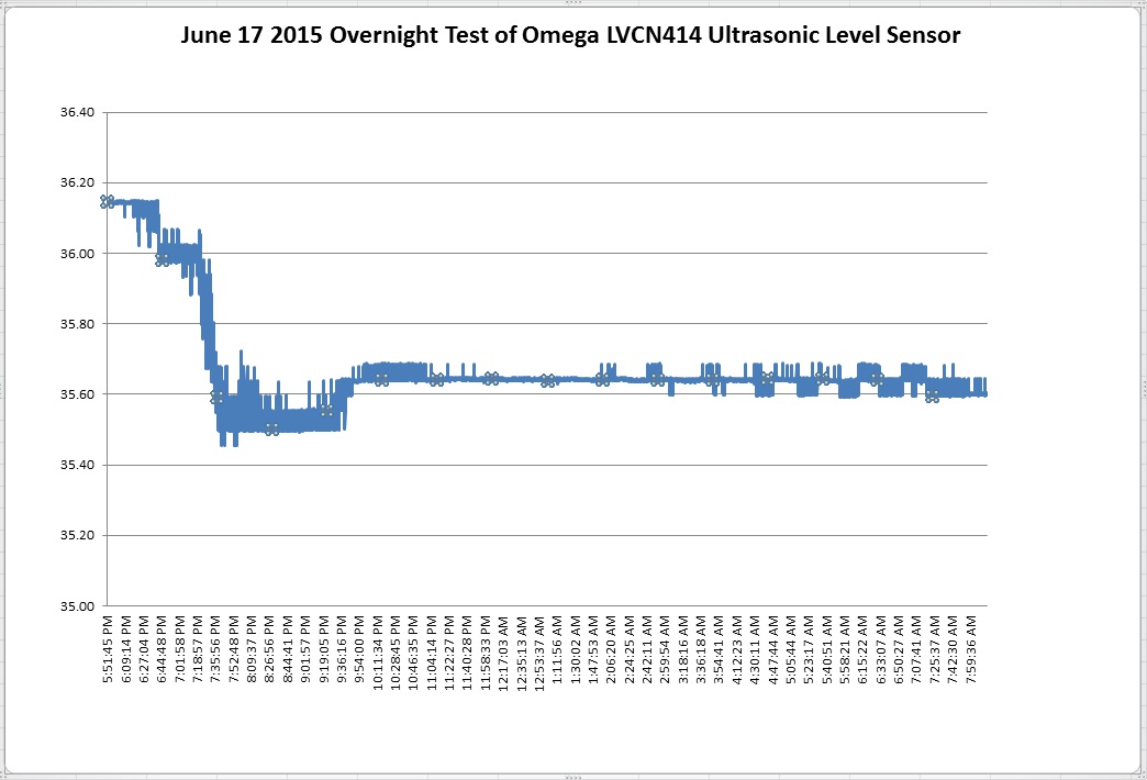
Isaac Earle | Development | Other | Controls | PLC Test of Ultrasonic Level Sensor |
The new T1/T2 level sensors (Omega LVCN414) were hooked up to the PLC and the test performed on June 11 was repeated.
The water level above the base of the bucket was measured using a tape measure, as well as with the level sensor at various intervals as the bucket was filled and then drained:
Tape Measure Level (cm) --- Reading from Ultrasonic Level Sensor (cm)
Empty --- 0
3.3 --- 3.3
6.7 --- 6.7
12.2 --- 12.2
20.5 --- 20.3
29.2 --- 28.5
36.6 --- 36.3 (Last measurement on June 17, left overnight, see graph below)
36.6 --- 35.6 (First measurement on June 18)
31.3 --- 30.2
22.0 --- 21.9
13.1 --- 12.3
7.3 --- 6.5
Empty --- 0
Data was recorded while the sensor was left overnight (see attached plot). After approximately 2 hours, the sensor stabilized and then fluctuated less than 0.1cm for the next 12 hours. Overall these tests proved that this sensor will be suitable for the intended application and the parameters used for configuration are appropriate.
|
|
178
|
Tuesday, October 06, 2015, 14:04 |
Isaac Earle | Other | Other | Controls | Instructions for loading display screen for T1/T2 |
The following instructions were provided by Graham Waters:
From diag5pc bootup
Password: cfzx29mkdr
Bring up a terminal (click on "terminal icon" left side of screen)
> su
> xpfk34yzjc
> chmod o+rw /dev/ttyS0
> chmod o+rw /dev/ttys1
Bring up terminal emulator GTKTerm
From booton left of screen
Click on Applications->Accessories->GTKTerm |
|
189
|
Monday, March 07, 2016, 18:22 |
Isaac Earle | Development | Target 1 | Controls | Preliminary Testing of T1 Control System Complete |
Preliminary testing of the new PLC control system and EPICS interface was completed today for the T1 target, T1 cooling package, and T1 collimator. All systems behaved as specified. This test did not include testing of any T1 thermocouples which will be included as part of the T2 test program to follow. This is not considered system commissioning, which will follow after all preliminary testing is complete and the commissioning plan document has been released.
A scanned copy of the T1 test plan with notes is attached. |
| Attachment 1: T1_Testing_Checklist_-_Complete_-_March_7_2016.pdf
|


|
|
190
|
Wednesday, March 16, 2016, 16:50 |
Isaac Earle | Development | Target 2 | Controls | Preliminary Testing of T2 Control System Complete |
Preliminary testing of the new PLC control system and EPICS interface was completed today for the T2 target, T2 cooling package, T2 collimators, and T1 thermocouples. All systems behaved as specified.
Review of the commissioning plan is currently underway.
A scanned copy of the test plan is attached. |
| Attachment 1: T2_Testing_Checklist_-_Complete_-_March_16_2016.pdf
|


|
|
194
|
Thursday, April 07, 2016, 16:44 |
Isaac Earle | Development | Other | Controls | T1/T2 Controls "Assembly Tests" Completed |
The T1/T2 Control System "Assembly Tests" (Document 118467 Release #1, Section 5) have been completed. The expected result, as written in the document, occurred for every test. The T2 Shield Thermocouple #3 (B1A:T2:TC3SHLD:RDTEMP) showed slightly erratic behaviour when viewing archived data. It is uncertain at this point whether or not it will need to be bypassed in the B1A:T2:TGTRDY interlock.
The official commissioning tests (Section 6) are currently on-going. |
|
202
|
Tuesday, June 21, 2016, 09:25 |
Isaac Earle | Development | Other | Controls | T1/T2 EPICS System With-Beam Testing |
With-beam commissioning tests were completed today by Tony Tateyama and Isaac Earle. The test results are attached in PDF format. These tests are described in Section 7 of the Commissioning Plan (Document-118467 Release #2). These tests were not part of the official commissioning, but intended as an additional check of system functionality with beam on, and to confirm that the CCS current protection system performs as expected.
Official commissioning of the T1/T2 EPICS system was completed in April 2016, with the results released in Document-131503. |
| Attachment 1: T1T2_EPICS_Section_7_Commissioning_Results.pdf
|


|
|
206
|
Tuesday, August 30, 2016, 14:09 |
Isaac Earle | Development | Other | Controls | T1/T2 PLC Code Update |
A new version of the T1/T2 PLC code has been uploaded to the PLC CPU. The main change in the new version is a fix to a bug related to the target MK# which may have caused the previous CPU crashes. The EPICS interface now needs to be updated so that no target information is displayed on the EPICS screens when there is no target installed, or jumpers for both MK1 and MK2 are detected. This must be tested during the next maintenance day. The appropriate tests are Section 6.4.1 Test #5 and #6 from Document #118467 |
|
210
|
Thursday, October 06, 2016, 12:16 |
Isaac Earle | Development | Target 1 | Controls | Expansion Tank High Level Warning Added |
An expansion tank high level warning has been added to the T1/T2 control system under Work Request #4011. The purpose for this new warning is to alert staff of an unexpected water increase in the unlikely scenario that a leak develops in the heat exchanger between the two fluids and CuALCW on the secondary side enters the target water system. The new thresholds for high level warn, low level warn, and low level trip have been set at 40cm, 30cm, and 25cm respectively. The nominal water level is 35cm. All thresholds were tested by adding water to the tank, or removing it. All responded as expected. |
|
217
|
Thursday, March 30, 2017, 09:48 |
Isaac Earle | Development | Other | Controls | T1/T2 control system de-glitching & target ID changes |
The following changes were made to the T1/T2 PLC control system:
- De-glitching system investigated and Tony discovered that it was programmed incorrectly: the de-glitch time was observed only when a PV changed from bad state to good, not the opposite (meaning there was actually no de-glitching in place since system start-up in 2016!). This was reversed and the following de-glitch times were programmed: 100ms for trip thresholds except 300ms for flow meter trips, and 2s de-glitch on all warning thresholds. The new system was tested with the PLC in simulation mode and seems to be working correctly. This should eliminate or significantly reduce nuisance warnings and trips from the system.
- PLC system code was modified so that the target version displays '???' when no target is installed instead of defaulting to 'MK1' (all target positions registered as 'plugged' with no target installed, so there was no danger to the system, but this was still confusing to operators) |
|
290
|
Thursday, May 05, 2022, 14:38 |
Adam Newsome | Maintenance | Target 2 | Controls | T2-MK1: profile monitor actuation check and repair to connector |
An attempt was made to actuation the T2 profile monitor, however it showed up in EPICS as being not present. Furthermore, the "Remote" indicator light on the physical controller was not lit up despite the switch being in remote mode. The limit switch indicator light was working.
Upon troubleshooting with Erwin Klassen, it was determined that a jumper was missing on the profile monitor control connector (on the target end, rear of bulkhead). The jumper shorts pins A and G on the mil-spec connector on the controller end, which is for 120 VAC supply, to indicate that the device is connected. T1-MK1 was checked - this jumper was present on T1-MK1, across pins E and F of the mil-spec connector, but was not present on T2-MK1. Otherwise the connectors were identical. It is suspected that it was accidentally omitted during maintenance in the past. Regardless, a new jumper was soldered in-place on T2-MK1 across pins E and F to replicate T1-MK1. The system functioned normally after this.
Attached photo shows the completed solder job - the current state of the connector on the rear side of the target bulkhead panel. |
| Attachment 1: T2-MK1_prof_mon_connector_-_rear_-_after_fix.jpg
|

|
|
325
|
Wednesday, March 15, 2023, 15:56 |
Albert Kong | Maintenance | Target 2 | Controls | T2 - M9 and M20 beam blocker actuation and vacuum test |
We tested the actuation of the M9/M20 beam blockers on the T2 monolith (3-4pm).
Vacuum levels remained steady throughout so the M20 o-ring replacement that was performed this shutdown was successful (see strip of 1ACG4 - vacuum gauge for T2 systems interlock).
Note: M20 was actuated by contacting the control room, while M9 (labeled T2 blocker) was actuated through the physical ASU on the ground level of the meson hall (see picture).
For future shutdown work: the air supply valve must be kept open (tab lifted up), otherwise the solenoids won't see pressurized air.
We ran into issues because the tab on the valve broke early into the shutdown and we didn't realize that it had to stay in the open position.
Note: The flow on the T2 demin line went up to 1.5 gpm yesterday when we were on the blocks. The needle valve was likely nudged on accident.
Update:
1) the T2 demin flow was corrected and the air supply tab was replaced - see picture M20
2) T2 BB actuated successfully with replacement tab - vacuum remained stable
3) slow leaking valve connections were tightened again
4) water level in expansion tank corrected to just below 40 cm |
| Attachment 1: 6577ca47-8221-4558-9aa0-50869de9b2f5.jpg
|

|
| Attachment 2: 20ff7546-2b80-4acc-b1d5-f22f6011762f.jpg
|

|
| Attachment 3: Screenshot_2023-03-16_085640.png
|

|
| Attachment 4: T2_Mar16_2023.png
|

|
| Attachment 5: 98899bdd-bc14-42f1-9798-e1b3258899a2.jpg
|

|
| Attachment 6: T2_Mar16_2023_2.32pm.png
|

|