 Friday, December 09, 2016, 14:58, Isaac Earle, North Hot-Cell, Development, , , NHC service area floor and top of roof block painted Friday, December 09, 2016, 14:58, Isaac Earle, North Hot-Cell, Development, , , NHC service area floor and top of roof block painted 
|
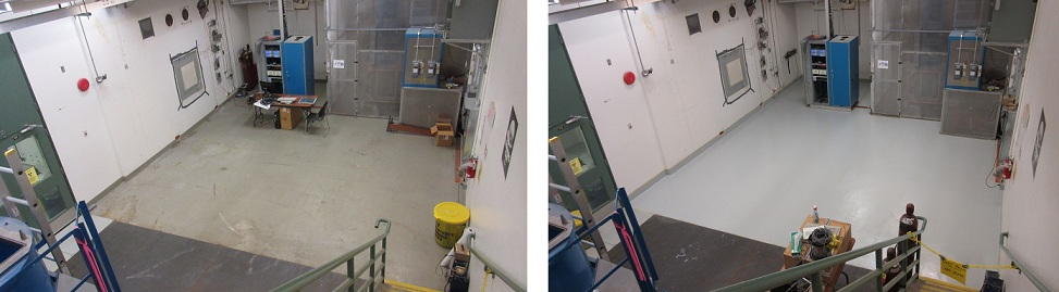
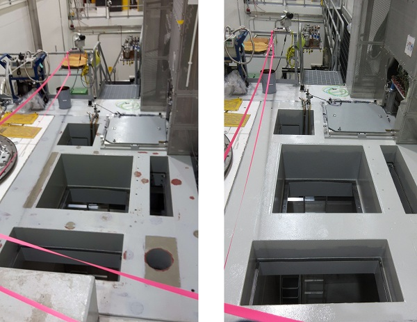
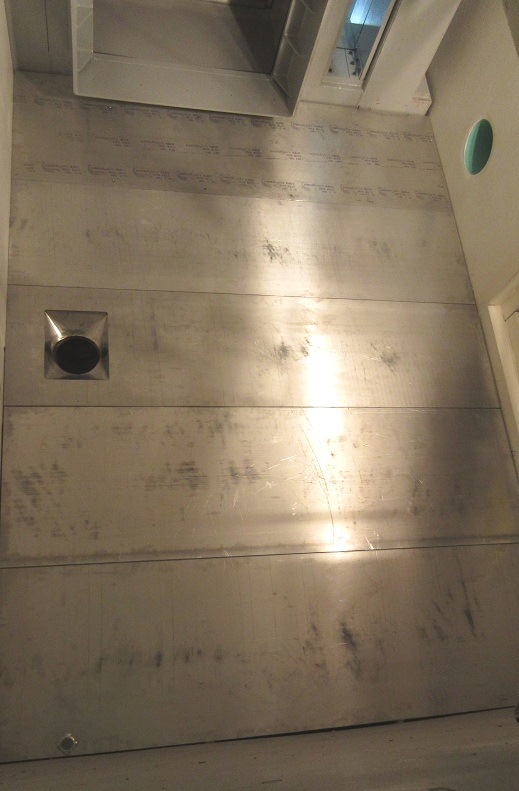
The concrete floor in the North Hot Cell service area and the top of the NHC roof block in the target hall have been painted with Macropoxy 646 oil based epoxy paint, colour Flint Grey. Two coats were used for the NHC roof, and one for the service area floor.
|
|
Friday, January 18, 2019, 10:26, Isaac Earle, North Hot-Cell, Development, , , NHC sealing improvements and repeat of RH test for LED lights
|
The following NHC development work was completed under WP I2019-01-09-4:
- Location of RH feature on operator level LED lighting updated to match IRH1800 Rev B design
- Remote Handling test of the LED fixtures was repeated using a 9' pole with hook attachment through the manipulator slave hatch from the Target Hall: both LED fixtures were removed and reinstalled successfully with relative ease
- Tool port seal replaced to address an audible air leak: the 1/4" foam seal was removed and replaced with adhesive backed 5/8" wide hollow foam rubber seal (McMaster Carr PN: 93085K81). Prior to the change DPG4 was at 0.63"wc, after the change wit was 0.73"wc with all system variables constant.
- NHC manipulator access block seal was replaced, likewise to address an audible air leak: the 1/4" foam seal was removed and replaced with adhesive backed 1/2" thick BunA-N rubber strip (McMaster Carr PN: 9023K85). DPG4 was at 0.94"wc prior to the change, and 1.07"wc after with all system variables constant
|
|
Thursday, March 02, 2017, 15:02, Isaac Earle, North Hot-Cell, Development, , , NHC roughing filter installed
|
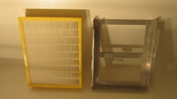
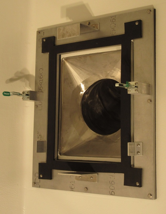
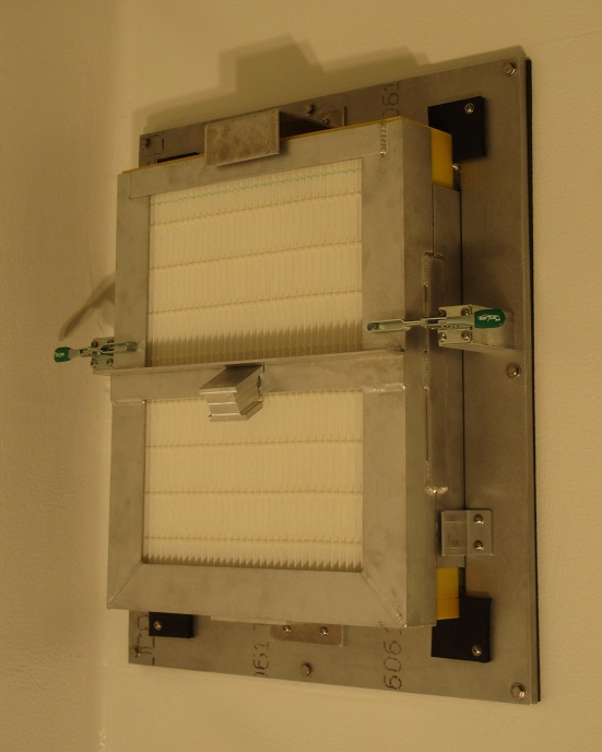
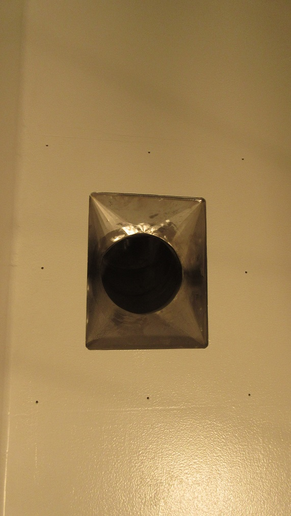
The roughing filter assembly (RFM0001D) has been installed at the ventilation exhaust hole on the NHC partition wall. The filter used is Model # 332-528-002 supplied by BGE Service & Supply Ltd (see PO # TR123998). Installation and removal of the filter using the manipulators will be tested after they have been installed.
|
|
Thursday, May 11, 2017, 16:10, Isaac Earle, North Hot-Cell, Development, , , NHC roof block to TH north wall gap sealed
|
The gap between the north face of the NHC roof block and the target hall north wall in the area where the NHC inlet ducting will be installed has been sealed with Sikaflex 1a flexible polyurethane sealant applied over foam backer-rod. |
|
Monday, December 10, 2018, 15:31, Isaac Earle, North Hot-Cell, Development, , , NHC remote connection testing with manipulators
|
The following tests have been successfully completed using the NHC manipulators:
- Ventilation pre-filter (mounted on the NHC/TCS partition wall) removed and re-installed using the manipulators
- Electrical plugs (two total) for operator-level LED lighting located on east wall of cell interior plugged in, and un-plugged using the manipulators
- Electrical plug inserted into and removed from each of the 120V outlets (four total) located in front of the viewing window using the manipulators
- All diagnostic service connections removed and reinstalled using the manipulators (six total, see IRH1765)
- All Staubli air and gas connections removed and reinstalled using the manipulators (five total, see IRH1749)
These tests were performed at various different times over the last several months by Isaac Earle and/or Chad Fisher. |
|
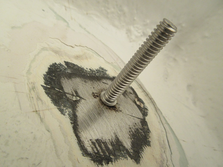
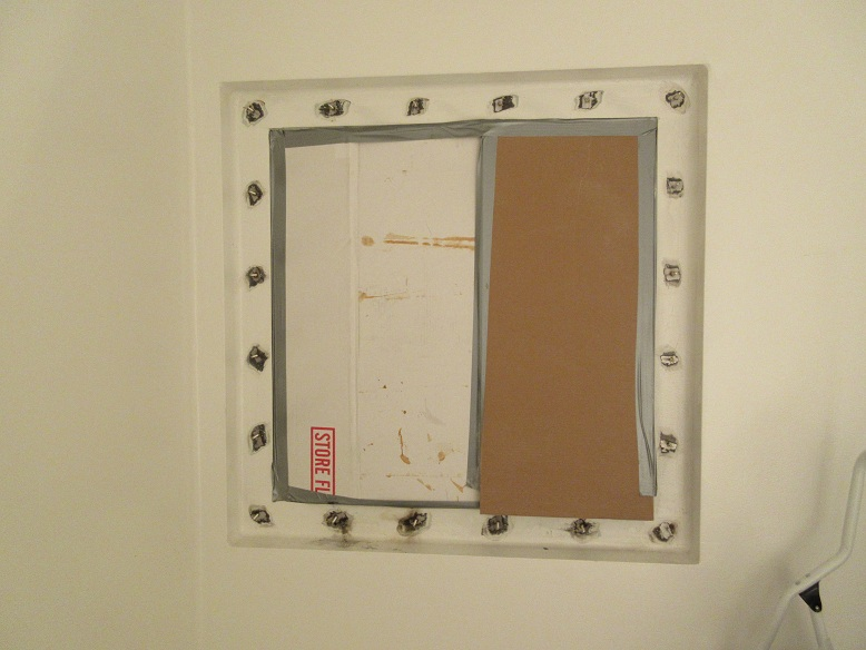
Tuesday, May 02, 2017, 09:48, Isaac Earle, North Hot-Cell, Development, , , NHC polycarbonate window cover panel installed
|
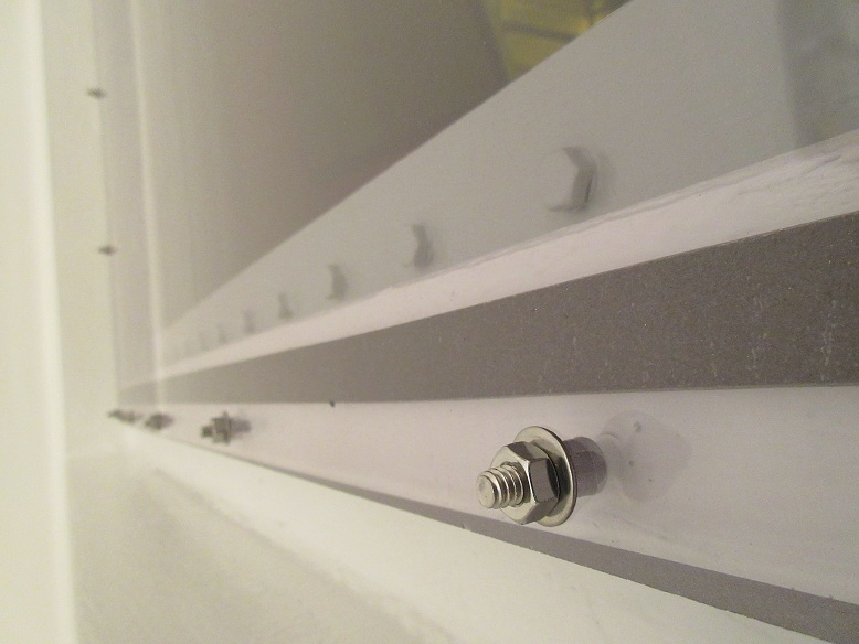
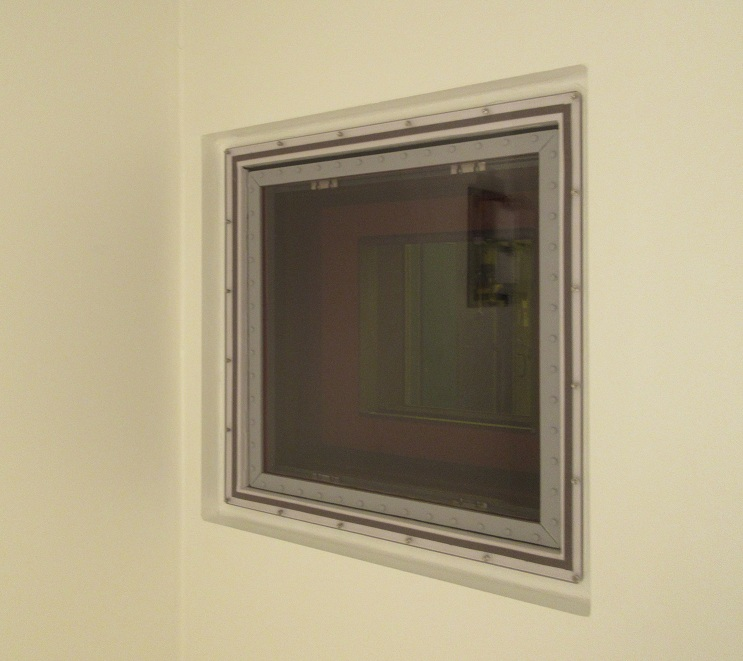
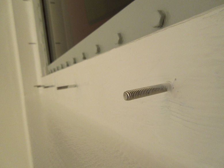
The window cover panel has been installed on the hot side of the NHC shielding window according to drawing IRH1638. It was necessary to drill and tap a hole in the steel frame first to achieve proper grounding for stud welding. The strength of all studs were checked by installing a nut on the stud tightened against a block up against the steel frame, which was then torqued to a minimum of 10 ft*lbs. For the final installation the nuts were each torqued to approximately 3 ft*lbs. Visibility from the cold side of the cell was checked before and after installation by Chad Fisher and Isaac Earle: no distortion was caused by the new cover panel and with the in-cell work lights aimed in a similar direction to how the permanent lights will be installed (shining down from the roof, and also aimed south from the periphery of the window) there was no significant decrease in visibility of the work space. A couple of small scratches are visible on the panel surface - these were already there when the panel arrived at TRIUMF. The panel has been installed in an orientation that will minimize the visibility of these scratches during normal work. When the work lights were aimed at the window many imperfections in the panel were visible, however this is not expected to occur during normal operation. After the cell lighting has been installed the visibility will be re-evaluated and a new panel can be procured if necessary.
|
|
Wednesday, January 18, 2017, 11:53, Isaac Earle, North Hot-Cell, Development, , , NHC partition wall installation complete
|
The final panels of the partition wall were installed today as per drawing IRH1609. Sealing, finishing, and painting of the NHC walls and floor can now commence.
|
|
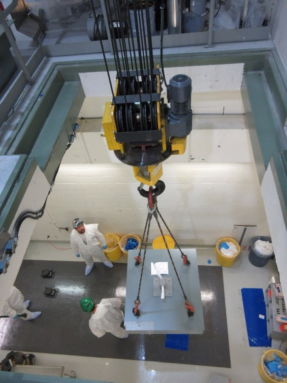
Friday, October 06, 2017, 11:12, Isaac Earle, North Hot-Cell, Development, , , NHC module port shield block and TCS vessel shield block installed
|
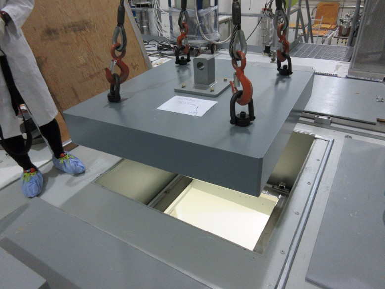
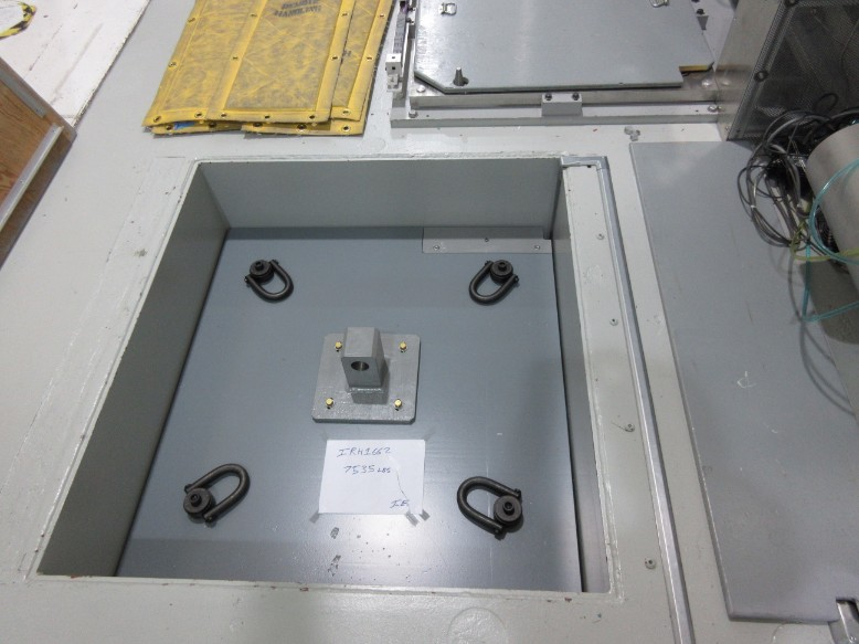
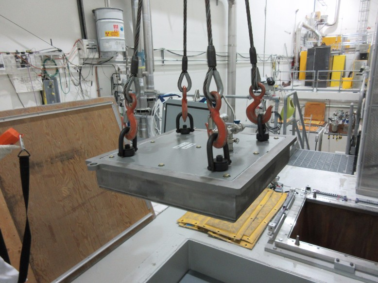
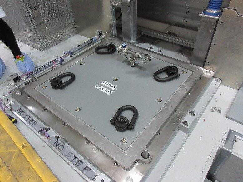
The NHC module port shield block (IRH1645) and the TCS vessel shield block (IRH1646) were installed yesterday in the target hall according to assembly drawing IRH1652. No issues were encountered during installation. Vacuum was pulled on the TCS and a leak check was performed on the shield: no leaks found.
|
|
Friday, June 23, 2017, 17:28, Isaac Earle, North Hot-Cell, Development, , , NHC module flange and cameras installed
|
The North Hot Cell module support flange (IRH1152D) was installed on June 21, 2017 using 1/8" rubber sheet as a sealing gasket. The rubber was glued at the seams with Loctite 495 instant adhesive. Cameras with all required wiring and connectors were installed on the mounting bars (IGN0325D) and then aligned to provide the same view as at other module installation locations in the target hall. A cable with 5 video signals, and a camera power cable was routed from the south wall in the target hall (where video line connections are), to the panduit on the north wall. An additional section of cable will be installed to link to the flange cameras after cable covers are installed on the floor.
|
|
Tuesday, December 18, 2018, 11:13, Isaac Earle, North Hot-Cell, Development, , , NHC manipulator slave-end swap, RH test, and various other work
|
The following North Hot Cell work was completed over the last week under work permit I2018-12-12-1:
Thurs Dec 13th:
- Prepared master side according to removal manual (noticed screwing in the right side locking screw was not as smooth to go in as normal; left side was smooth like normal)
- Removed manipulator roof block and set down in yellow frame (required some stacked wood to prevent light from bottoming out)
- Removed steel side plates in NHC manipulator hatch
- Removed the slave end (SN: 9764) – noticed “Right Elevation/Twist Coupler” off of vertical by around 30 degrees
- Wrist elevation of removed slave end was not locked, lifted it slightly and this brought the coupler to the vertical position and it locked with a click
- Suspected the thru-tube also would be misaligned, confirmed by inspecting visually in hot cell (Unsure why this misalignment occurred considering we followed the removal procedure properly. One theory is that when we accidentally left the timing screw in the master side handle cable drum last time it may have caused things to get a little out of alignment)
Friday Dec 14th:
- Un-did the right side locking screw on the master
- Then could turn coupler on the thru-tube to the vertical position from within the hot cell
- Re-locked the right side locking screw (this time it went in smoothly)
- With all couplers on thru-tube vertical we then installed the replacement slave (SN: 9352) as per instructions
- For future slave end changes should use some sort of long chain or sling instead of having the auxiliary crane hook block within the hatch (some sort of T-hook type lift feature replacing the bail may work better as well)
- Evaluated the manipulator: seemed to be working normally, Chad tested plugged in LED lamp plug and also opened and closed the work table hatch
- Noticed Z motion tape on slave end loose when fully extended in Z (nice and tight when retracted) – this seems to be normal
- Confirmed manipulators can reach all surfaces of the table
- Then tested remote handling of LED light fixtures from the Target Hall using pole tools through the manipulator roof hatch
- Started with both LED light plugs un-plugged
- Used 9’ standard beam lines RH pole tool (this worked fine, but 10-12’ would be better)
- Curved hook end attachment
- First lifted cables out of all cable tray sections (the wall mounted Panduit)
- Then removed the East light fixture assembly (IRH1800) - lifted from designated lift loop (IRH1796) – This went smoothly
- Hoisted up into the Target Hall, then lowered back down to re-install
- To reinstall had to hook the assembly at a lower point due to flex of the pole from the weight of the assembly (hooked just below the ballast for installation). Using this method reinstalling the fixture went smoothly. I will update the design to move the designated lift point (or add an additional one) at this location.
- Once the light fixture was on the bracket, replaced the cables in the cable tray using the pole tool. The final section on the east wall before the outlets was a little tricky, but by viewing and reaching from the north-west corner of the hatch it was do-able
- Confirmed visually that remote removal and installation of the west fixture can be done using the same procedure as the east
- Replaced lamp block (stored lifting hardware for hatch side plates above block, below hatch cover)
Monday Dec 17th:
- Left side slave-end boot was installed as per manual instructions. It was done with two people inside the cell this time which went much smoother than just one last time (the boot was not installed on the slave prior to moving it into the hot cell because we wanted to inspect the tape and cables after installation and the boot would prevent that)
- The condition of both boots was checked. Both appear to be in new condition with no signs of degradation. The material seems pliable and strong.
- Chad Fisher, ISAC Hot Cell Operator, checked the light level from the cold side of the hot cell and confirmed that it is acceptable. However, without the operator level LED lighting it was too dim.
Tuesday Dec 18th:
- Lift bails for both manipulator slave ends set to farthest north position which results in face that mates with thru-tube to be close to vertical when hanging from lift bail
- Work table, stairs, entrance floor area, pre-filter assembly, tool port, window cover, and hot side service connection panel vacuumed and wet wiped to remove dirt and dust.
- NHC inlet damper (located in Target Hall) adjusted to set NHC depression to around 1.05”wc (the NHC damper is currently not responding to the NVCS and needs to be investigated and repaired by Controls Group and/or Mechanical Services)
|
|
Friday, December 01, 2017, 16:42, Isaac Earle, North Hot-Cell, Repair, , , NHC manipulator service visit
|
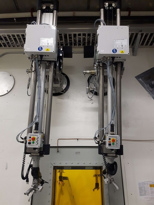
Pete Dudley, manipulator service technician from CRL, was on site from Nov 27-30 to service the NHC Model N manipulators (See E-log entry #1578 for background).
He began by evaluating the motion selection and electric drive of the manipulator installed on the blue service cart. This manipulator had chip A0166R01, same as the right side manipulator which had the failure described in E-Log 1578. Pete noted that the arm was very slow to switch between the different drive directions, and had a significant lag between when the switch for motion was released, and when the motor actually stopped driving. This was the case with all directions. Because of this, he suspected that the right arm Z tape broke because when the manipulator reached the switch at the end of travel, the motor did not stop quickly enough causing over tension and snapping the tape. A newer chip, A0166R04, was removed from the spare master arm (received Spring 2017), and installed into the master arm on the blue cart. The test was repeated, and this time the motion selection and drive worked as expected. The situation which previously caused failure was evaluated: slave end fully extended in Z, master end fully collapsed in Z. In this configuration the arm was moved back and forth in the Y direction. No tape failure occurred, and the Z motion tape tension seemed normal. Y motion drive was attempted, and was not possible, as expected. This test was repeated in the opposite configuration (slave end fully collapsed, master end fully extended) with the same results. Full drive speed was used for all tests.
The right side slave arm (with broken Z tape) was then removed and transported to the HCSA. Using the bench mounted locking plate, the broken Z tape was replaced, and a full inspection and cable/tape tensioning was performed. Pete accidentally broke the Z tape on the right side master arm while investigating the failure, which was also replaced.
The other two slave arms were also both inspected, tensioned, and tested in the same way. Then all three were each in turn installed to the master arm #9348 on the blue manipulator transport cart where all mechanical motions and drives were tested (except X, because mounted on cart), the failure situation described above was also tested for all three slave arms.
The left side manipulator was then installed into the wall. It was necessary to remove the lead sheilding on the thru-tube and machine it down approximtaely 0.070" in order for the arm to fit into the wall tube. After installation, the manipulator motions and drives were tested again including the X motion, and the failure scenario situation was also re-tested. Chad used the left side manipulator to remove and re-install the pre-filter mounted on the west side partition wall. He also confirmed that he could reach the east wall electrical outlets and the outlets, gas fittings in front of the window.
The right side slave arm was adjusted so that the Y position was moved 1/2 turn of the shaft drive towards the window (this is the maximum adjustment possible before it hits a hard stop). This was done so that the operator can more easily reach the outlets and air/gas connections inside the cell in front of the window. Because both the master and slave ends protrude further out from the wall compared to the E-HD manipulators for the SHC, this modification makes the NHC manipulators feel a bit more like the SHC manipualtors for the operator. After the adjustment, the right side slave arm was installed. The left side slave arm was removed, adjusted the same as the right side, then reinstalled. The spare slave arm was also adjusted in the same way.
The right side manipulator was evaluated through all mechanical motions. We attempted to remove the A0166R04 chip from the left side, and install in the right in order to try the motion drives, however the pins had been damaged from the previous removal/install, and eventually one pin broke so this was abandoned. CRL will ship us at least three new A0166R04 chips which should arrive in 2-3 weeks.
Upon completion of the work the location of the different arms is as follows: Right side master #9351, Left side master #9348, Spare master #9763, Right side slave #9349, Left side slave #9764, Spare slave #9352
|
|
Friday, February 24, 2017, 15:12, Isaac Earle, North Hot-Cell, Development, , , NHC interior walls/floor/ceiling re-finished, sealed, and painted 8x
|
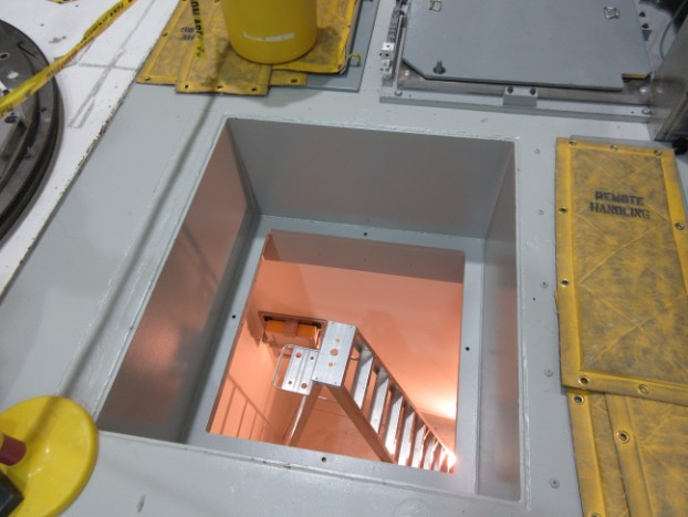
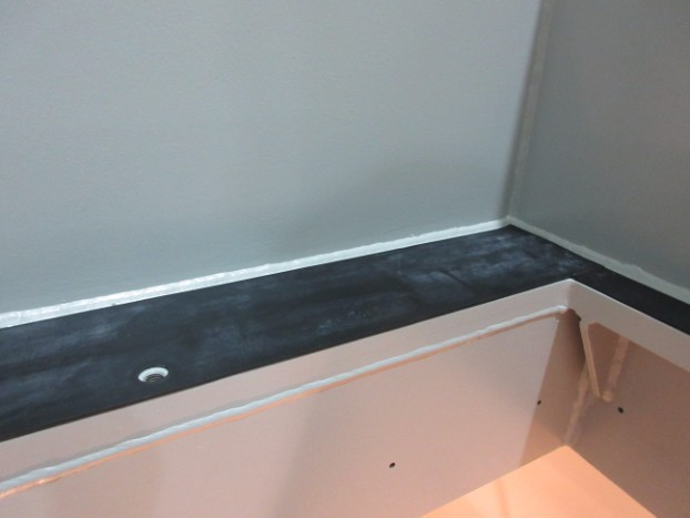
The North Hot Cell interior walls, floor, and ceiling were re-finished, sealed, and painted by Omni Coating from Feb 6 - 17 under PO #3036471. This job required 2-3 people for 4-6 hours per day over the 2 week period. First the existing surfaces were ground and/or sanded to remove existing coatings and protrusions/sharp edges. This was followed by a coat of primer to highlight uneven surfaces and improve adhesion of following fillers and coatings. Metal shims between the cell walls and roof were cut away where they protruded into the cell. Loose steel cylinders between SHC and NHC spaces were fixed in place using epoxy filler. Epoxy or polyurethane fillers were used to fill all gaps, cracks, holes, etc, as detailed below. Foam backer rod and polyurethane filler were used to seal all large wall-to-wall and ceiling-to-wall gaps. An approximate 2cm radius rounded corner was formed at all wall-to-wall and floor-to-wall corners using polyurethane sealant. The interior of the tool-port, personnel access hatch, as well as the north roof hatch were also re-finished with the same procedure. After all sealing and finishing work the surfaces were coated with "Mill White" Macropoxy 646 Fast Cure Epoxy Paint as per manufacturer instructions. Note: this paint is recommended by the manufacturer for nuclear applications and has been tested for decontaminability: 99% water wash; 95% overall as per ASTM D4256/ANSI N 5.12 as well as for radiation tolerance: Passed ASTM D4082 / ANSI 5.12 with a 525 micron thick coating.
The following products were used as described (data sheets attached):
Sanitile 120 Universal Acrylic Primer - 50-75 micron dry film thickness coat applied over all existing ceiling, walls, and floor surfaces after preparation by sanding
Sika Duochem 8107 Epoxy Paste - Used for filling voids and cracks in concrete surfaces
Sikaflex 291 Polyurethane Elastomeric Adhesive and Sealant - used for caulking joints and cracks in the concrete walls and aluminum panel wall and for creating radiused corners in wall-to-wall and wall-to-floor corners
Macropoxy 646 Fast Cure Epoxy Paint - 4 coats applied on all surfaces using rollers or brushes to create a total thickness of 525 microns as per data sheet

|
|
Thursday, June 15, 2017, 11:29, Isaac Earle, North Hot-Cell, Development, , , NHC inlet ducting installed
|
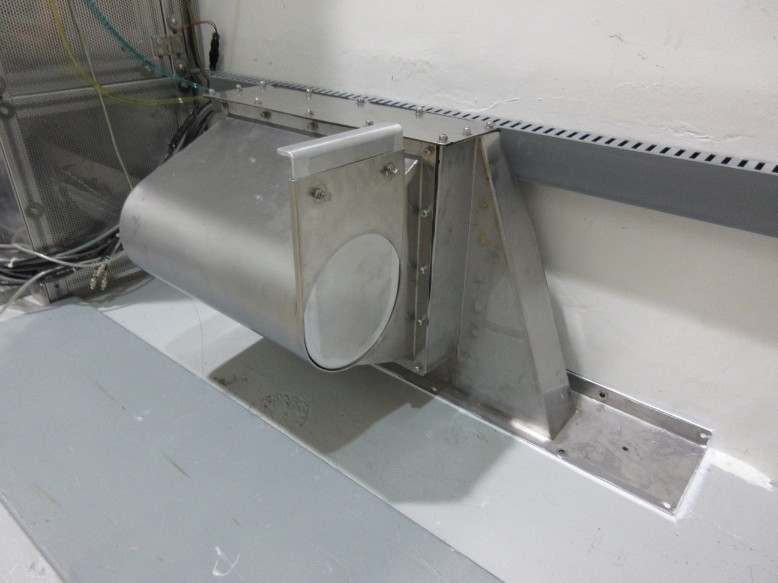
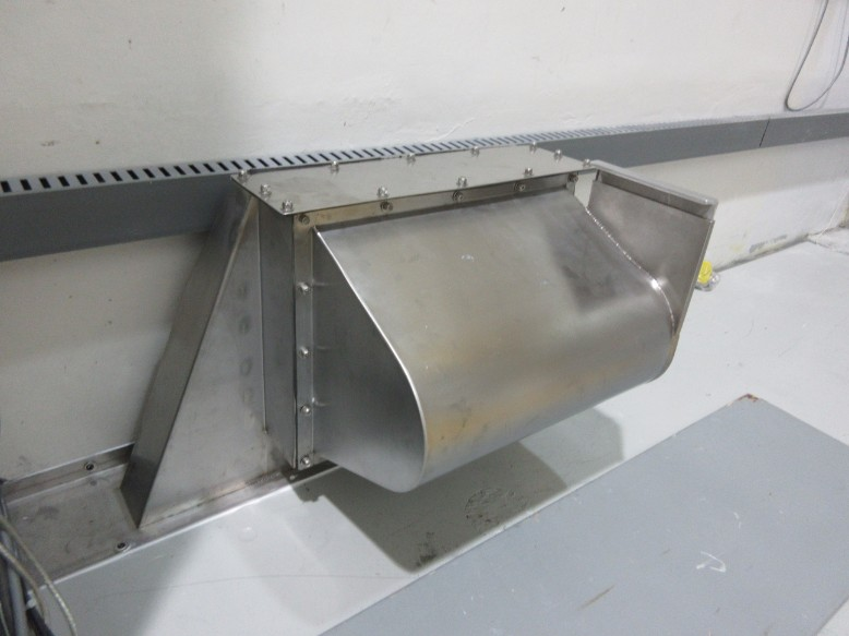
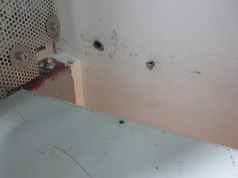
The North Hot Cell inlet ducting assembly was installed today in the target hall at the north end of the NHC roof block. A small section of the perforated aluminum sheet on the TCS cage had to be trimmed for the assembly to fit (see IMG_0214). At each end of the assembly it was fastened to the roof structure using a 1/4"-20 tapped hole in the steel roof, and a 1/4"-20 anchor in the north wall of the target hall. The base flange of the assembly was sealed to the roof structure and TH wall using Sikaflex 1A polyurethane sealant on all sides.
|
|
Monday, January 21, 2019, 16:27, Isaac Earle, North Hot-Cell, Development, , , NHC in-cell camera wired to right side monitor
|
The NHC right side monitor has been wired to display the signal from the in-cell camera. This was tested using a snake camera on both of the CPC-4 connectors.
|
|
Thursday, January 31, 2019, 14:16, Isaac Earle, North Hot-Cell, Development, , , NHC grounding approval
|
Franco Mammarella was consulted regarding electrical grounding of the NHC design (RS103 of Document-131915). After discussing the design, and having grounding inspected by Randy Boehm, Franco approved the design and advised that the grounding system should be inspected periodically. This task has been added to the Remote Handling inspection index on an annual schedule. A PDF copy of the e-mail correspondence with Franco is attached. |
|
Thursday, September 13, 2018, 16:57, Isaac Earle, North Hot-Cell, Development, , , NHC grounding and mili-ohm testing
|
The following equipment has been connected to the building ground located in the Target Hall by the TCS using 1/2" flat bonding strap:
- NHC roof structure
- NHC/TCS partition wall
- NHC work table
The following equipment has been connected to the building ground by connecting to the work table inside the NHC using 1/2" flat bonding strap:
- Air and gas supply line mounting bracket inside NHC
- Receptacle box mounting bracket inside NHC
- Diagnostic signal box mounting bracket inside NHC
The resistance between the following locations and the copper grounding plate located at the base of the NHCSA north wall were measured. The resistance of the wire used was 258.10mΩ, and has been subtracted from the following results.
Measurements taken in NHCSA:
- Control panel below viewing window (base plate of box): 4.67mΩ
- Oil window frame (bare metal drain valve): 55.34mΩ
- Left manipulator (ground plate near e-stop button): 73.46mΩ
- Right manipulator (ground plate near e-stop button): 202.58mΩ
- Air and gas supply line mounting bracket: 40.68mΩ
- Diagnostic connector box: 12.15mΩ
- Steel conduit for 110V supply to hot cell interior: 4.81mΩ
Measurements taken inside NHC:
- Work table: 4.51mΩ
- Pre-filter bolted to partition wall: 4.84mΩ
- Table hatch lid: open load
- Left manipulator thru tube: 515.8mΩ
- Right manipulator thru tube: 342.0mΩ
- Left manipulator (slave boot plate bolt): 885.9mΩ
- Right manipulator (slave boot plate bolt): 1444.0mΩ
- Grounding strap for air/gas plate: 4.84mΩ
- Outside of SHV connector on diagnostic signal box: 4.56mΩ
- Exterior of 110V electrical conduit: 3.88mΩ
- Male Staubli connector for 1st gas line: 53.7mΩ
- Welded stud for window cover panel: 6.06mΩ
- Grounding strap for partition wall: 4.39mΩ
- Roof structure (measured inside un-painted bolt hole): ~0mΩ
- Stainless steel module flange: ~0mΩ
Dedicated grounding will be added in the near future for the oil window frame and the manipulator thru-tubes. Testing will then be repeated for those items.
Dec 18, 2018 update:
The oil window frame and both manipulators (where they bolt to the thru-tubes) were connected to the building ground using 1/2" flat bonding strap connected at the cold side of each piece of equipment, and running to the grounded copper sheet located in the NHC service area at floor level. The connection is made inside the electrical racks located directly west of the NHC operator area on the cold side. This work was done by Travis Cave in October 2018.
Mili-ohm testing for these items has not yet been repeated.
Jan 14, 2019 update:
Grounding was added from the metal plate near the e-stop button on the master arm of both manipulators. The same 1/2" flat bonding strap was used which was tied into other bonding strap which runns to the grounded copper sheet in the NHCSA.
Mili-ohm testing was repeated for the following items:
- Oil window frame (bare metal drain valve): 13.6mΩ
- Left manipulator (ground plate near e-stop button): 16.1mΩ
- Right manipulator (ground plate near e-stop button): 16.5mΩ
|
|
Thursday, March 04, 2021, 16:30, Isaac Earle, North Hot-Cell, Development, , , NHC gas delivery lines leak checked
|
The North Hot Cell gas delivery lines (labeled 1, 2, and 3 on the hot and cold side panels) were leak checked today. 5psi helium gas was applied to each line in turn with the appropriate solenoid valve opened and a Staubli connector with plastic tubing and the leak check wand attached to the matching connector inside the cell. The end of the wand was sealed using tape. The Agilent G8601 leak detector was used on "sniffing" mode to check for escape of helium gas from all joints and connectors. With the sniffing line attached the leak detector test port pressure was 3.9E-1 Torr and the baseline leak rate was 1.7E-6 Torr*L/s. There was no response while testing all of the three lines. For all three there was a leak detector response after disconnecting the Staubli fitting, which confirmed that the lines were properly charged with helium. |
|
Tuesday, February 28, 2017, 17:51, Isaac Earle, North Hot-Cell, Development, , , NHC flanged ducting connection sealed
|
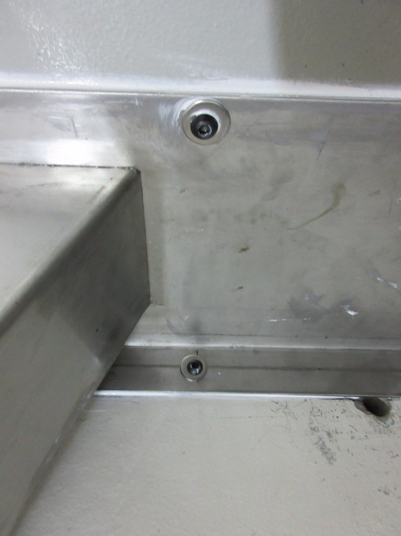
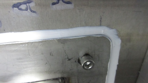
The North Hot Cell ducting (IRH1617) has been sealed with a bead of Sikaflex 1a polyurethane construction sealant where the flanged connection bolts to the NHC/TCS partition wall. When this sealant shows signs of aging it may be cut away and re-applied without unbolting the flange.
|
|
Tuesday, April 11, 2023, 11:35, chad fisher, North Hot-Cell, Standard Operation, , , NHC fields post sample removal
|
The fields in the NHC after removal of Ferran's graphite sample is 238 uSv/h. This again seems to emanate for the items in the 5 gal pail...the copper tubing from the beam window or, as I mentioned in my previous elog, the peek samples. I did ask about removing these during the graphite sample removal but was told they were not "hot". |
|
Tuesday, April 18, 2023, 07:28, chad fisher, North Hot-Cell, Maintenance, , , NHC entry summary
|
NHC was entered on April 17, 2023 for inspection and maintenance. Summary :
Compressible and non-compressible waste was loaded into a 55 gal drum and removed from the NHC. This same drum will be inserted into the SHC at a later date to be sorted, compressible waste compressed, and drum filled more.
Manipulator remote end tong cables checked. Tong cables didn't show any wear but both east and west had tong cables had hopped off the third highest pulley (see detailed write up . This was fixed by tying the tongs in the closed position to provide slack in the cables then inserting a t-handle through the wrist and offering the cables back onto the pulleys. Cable hopping is most likely due to aggressive ratcheting and releasing of the tong during operation.
Manipulator booting flanges were removed from both manipulators as it was previously found that the booting interferes with access to the inside of the containment box so it could not be used. Flanges were remove to provide even more clearance.
Containment box cover removal arm - linkage fasteners were removed one at a time and blue locktite added then reassembled and tightened appropriately to allow arm to swing freely (see detailed write up) . Lack of locktite during initial assembly was allowing fasteners that pass through bushings into the linkage arms to loosen over time/cycling.
Exhaust pre-filter changed.
Target insertion jig - The target insertion jig was rumored to had a missing fastener. A loose nut was found that appeared to belong to it but after much inspection a location for it could not be found...i.e. all parts appeared to be counted for. During this inspection it was noted that some over the fasteners in the main hinge were loose. Again these were removed one at a time, blue locktite added and fasteners tightened to allow proper movement (see detailed write up).
Window inspected for leak. No sign of any leakage from the "hot" side.
|
|