 Friday, July 12, 2024, 08:51, Riley Sykes, Safe Module Parking, Maintenance, , , SMP chain guard Friday, July 12, 2024, 08:51, Riley Sykes, Safe Module Parking, Maintenance, , , SMP chain guard
|
SS washers were added to all slotted holes on SMP chainguard cover plate |
|
Thursday, January 09, 2025, 11:46, David Wang, Safe Module Parking, Standard Operation, TM4, No target, SMP is under vacuum for TM4 storage during shut down.
|
SMP:MP1 is started with SMP BV1 is opened. SMP is under vacuum for TM4 storage during shut down. |
|
Monday, February 03, 2025, 13:04, David Wang, Safe Module Parking, Maintenance, , , ITW/ITW 24VDC electrical connectors for TP BVs MRO.
|
ITW/ITW 24VDC electrical connectors for TP BVs MRO has been done. |
Thursday, February 20, 2025, 10:12, David Wang, Safe Module Parking, Standard Operation, TM4, No target, TM4 electrical check at SMP(vented) without target 
|
TM4 electrical check at SMP(vented) without target: PQ is dead short to RU. PQRU to 60kv bias,750Kohm at250V. other things are good. Notes: In attachment files all hand writing and circled TM2 should be TM4. the results are measured on TM4 not TM2. |
|
Friday, June 20, 2025, 10:46, Jason Zhang, Safe Module Parking, Maintenance, , , Annual electrical and mechanical inspection of Safe Module Parking
|
An annual electrical and mechanical inspection was performed on the SMP on 2025-06-20. The following items were checked:
- Check condition of wiring for physical/radiation/UV damage
- OK, no signs of significant damage
- Check for cable tray debris or damage
- Check inside control panel: components and wiring, labeling
- Labeling intact, components in good condition
- Misc. random wires pulled to check... OK
- Check connectors for damage
- Check pendant for damage and verify labeling intact
- Lid open/close test
- Lid was opened and close multiple times - smooth operation, no concern
- Lid close logic was checked - OK
- Vessel rotation and limit switch check
- Both CW and CCW limits were checked, functioning
- No concern on rotation - chain drive, rotary limit switch, and cable reel all functioning normally
- Inspect tensioners
- Visual inspection
- Lid Bearings
- Noticed a missing grease nipple so a new one was installed.
- Applied grease to the bearings although it may not be necessary due to the movements allowed in the lid mechanism.
Overall the inspection was successful.
Photos can be found in G:\remote handling\Facilities and Projects\ISAC\Mini Storage Vault\Inspections |
|
Wednesday, December 18, 2024, 14:17, Adam Newsome, Pail Handling Tool, Maintenance, , , Pail Handling Tool - Inspection
|
An informal inspection of the main Pail Handling Tool was performed today as the final one for the year. Note that the main formal annual inspection was performed June 18, 2024 for this year.
The attachment to this e-log serves as a record of all inspections for this tool throughout 2024.
The spare tool was not inspected as it was not in service this year. |
|
Wednesday, May 04, 2016, 11:14, Isaac Earle, North Hot-Cell, Development, , , North Hot Cell Scope Decision
|
A meeting was held on May 4, 2016 to determine the scope of the North Hot Cell project. The following was agreed upon by those in attendance:
The NHC will be a designated target change hot cell. It will be capable of performing all routine target operations (target removal/installation, leak check, electrical check, video inspection, post irradiation examination, target waste packaging and removal) using the same method currently used in the south hot cell. Provisions will be included for the ability to perform target waste separation in the future unless a significant obstacle is encountered in which case the meeting attendees will be consulted. Target waste separation involves separating the internal target heater from the target heat shield, then combining multiple target heaters in a single F-308 shipment. Neither an inert gas atmosphere nor a double-door waste transfer system will be part of the NHC scope.
The following people were in attendance: Bob Laxdal, Anders Mjos, Don Jackson, Joe Mildenberger, Friedhelm Ames, Alex Gottberg, Grant Minor, Yasmine Saboui, Peter Kunz
The following people were invited, but were unable to attend: Chad Fisher, Pierre Bricault
The project will begin immediately, with Isaac Earle as the project leader. The first steps will be to submit a Project Initiation Sheet, then to write and release the Requirements Specification document. |
|
Friday, July 29, 2016, 14:27, Isaac Earle, North Hot-Cell, Development, , , North Hot Cell Measurements & Cleanup
|
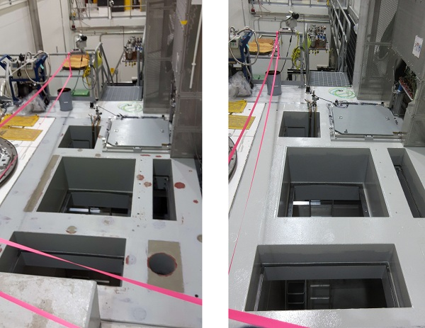
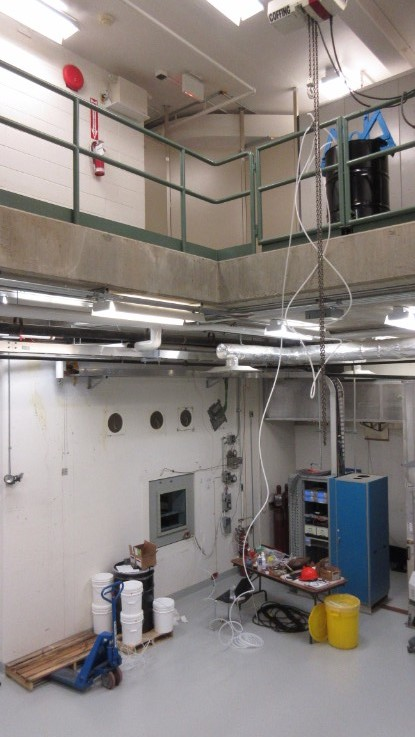
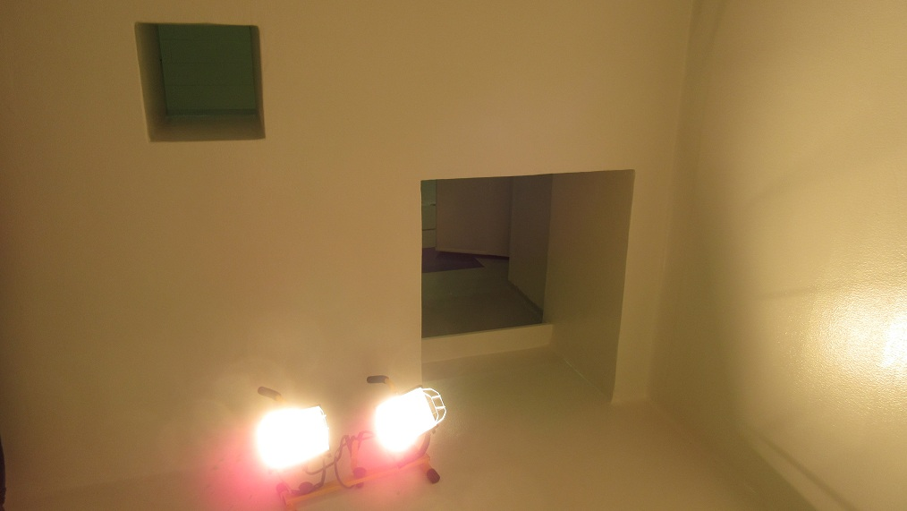
The North Hot Cell was accessed today via the Ante Room for inspection, measurements, and clean-up. There were no modules in the SHC or TCS, and no spent targets in the SHC. Under these conditions the maximum field in the NHC was approximately 2μSv/hr. The inside of the cell was cleaned and swept, followed by a floor swipe to check for contamination (none found). All areas of the ante room floor were also swiped: no contamination found.
The following measurements were taken in the NHC for comparison with the Soldiworks model:
SHC/NHC feedthrough panel fastener size: 1/4"-20, 1/2" long
NHC west wall to east edge of SEG block: 33-1/4" on south side, 33" on north side
NHC west wall to furthest extent of TCS (IRH1170): 40"
NHC west wall to wall indentation for viewing window: 46-7/8"
NHC west wall to end of existing ventilation duct: 4-1/8"
|
|
Friday, August 05, 2016, 14:13, Isaac Earle, North Hot-Cell, Development, , , Preparations for NHC Ventilation Test
|
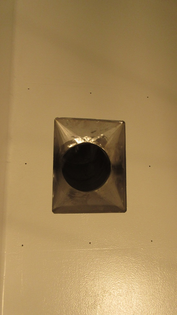
A hole was drilled in the NHC exhaust duct in the east end of the target hall above the hatch to the Ante Room. This will be used for measuring NHC exhaust flow rate with a thermal anemometer. The hole was tapped and plugged with an NPT tap.
Flow was measured in the existing hole in the SHC exhaust duct in approximately the same location. Flow velocity was measured to be 1415 ft/min with the lid on the SHC. Using duct ID 7.75", and assuming the average flow velocity is 90% of the flow at duct center, the flow rate was found to be 417cfm. We will attempt to match this figure for the NHC when the ventilation tests are performed. The tests have been scheduled for the maintenance day on Tuesday August 9th.
The anemometer probe and SHC test port plug were checked for contamination: none found. |
|
Wednesday, August 10, 2016, 14:38, Isaac Earle, North Hot-Cell, Development, , , North Hot Cell Ventilation Test Results
|
Testing was performed on August 9th on the ISAC nuclear ventilation system to determine if the existing ventilation system can achieve the required cell depressions for both SHC and NHC under all expected configurations and if a proposed modification to the DDC control system can provide acceptable stability and response time for the system. The proposed control system observes the lower of the SHC depression or the NHC depression + 10% (to avoid stability issues), and adjusts the dampers to try to achieve 250Pa (1.00" WC) depression in the area it is observing. With the proposed control system the SHC and NHC dampers are programmed to be at the same position, but can be tuned with a bias between them if required to achieve all ventilation requirements. The NHC and SHC dampers are programmed with a limit at 90% of the fully-open position. There is a damper in the ducting system in the section of duct after the SHC and NHC legs join together; this is set at 50% open, and was not adjusted during the the tests. Test summary and results are listed below:
1. Prior to switching to SHC+NHC control mode, the flow rate and depression of the SHC was measured with the lid on: 266Pa cell depression, damper 47% open, duct flow 417cfm. The lid was opened and the measurements repeated: 35Pa, damper 90% open, duct flow 630cfm (results in 83ft/min, 0.42m/s average flow velocity across HC module opening)
2. The control system was switched to the new SHC+NHC single control loop system. Measurements were taken with both hot cell lids closed. SHC: 246Pa, damper 72% open, 350cfm flow rate. NHC: 257Pa, damper 72% open, 510cfm flow rate. The ventilation fan speed was then increased from 53Hz to 57Hz (maximum speed is 60Hz). Measurements were taken with both hot cell lids closed. SHC: 257Pa, damper 51% open, 353cfm flow rate. NHC: 257Pa, damper 51% open, 515cfm flow rate.
3. The SHC module port lid was opened and the NHC lid left closed. SHC: 37Pa, damper 90% open, 462cfm (results in 61ft/min, 0.31m/s average flow velocity across HC module opening). NHC: 249Pa, damper 90% open, 551cfm.
4. The NHC module port lid was opened and the SHC lid closed. SHC: 203Pa, damper 90%, 360cfm. NHC: 33Pa, damper 90%, 648cfm (results in 85ft/min, 0.44m/s average flow velocity across HC module opening). The fan speed was then increased to 60Hz (max speed) to see if the depression setpoint for the SHC could be achieved in this configuration. SHC: 231Pa, damper 90%, 389cfm. NHC: 29Pa, damper 90%, 705cfm (results in 93ft/min, 0.47m/s average flow velocity across HC module opening)
5. Both SHC and NHC module port lids were opened and the fan was left at 60Hz. SHC: 31Pa, damper 90%, 448cfm (results in 59ft/min, 0.30m/s average flow velocity across HC module opening). NHC: 29Pa, 90% damper, 669cfm (results in 88ft/min, 0.45m/s average flow velocity across HC module opening)
For all tests the control system arrived at a stable depression value in less than 5 minutes, and thereafter exhibited only minor fluctuations.
It was observed that when the fan speed was increased to 57Hz, and for the duration of the tests, there was negligible change in the depression and damper positions for the mass separator room and target pit area.
The HEPA filter in the SHC leg of ducting has not been changed since commissioning of the facility (~15 years), and the SHC charcoal filters have not been changed since installation approximately 5 years ago. The SHC pre-fitler located inside the cell was changed in January 2016. When these are changed (which should be done before commissioning of the NHC ventilation system), the difference between SHC and NHC flow rates should decrease, and the SHC depression with NHC open should increase (likely up to the 250Pa setpoint).
Conclusion: The new SHC+NHC single control loop system effectively controls the system under all conditions tested. The existing ventilation system achieved the required NHC depression (250Pa, from RS 50, Document #131915) with both cells closed, and with SHC open only. The same depression for SHC with both cells closed was achieved with both cells closed, but only reached 231Pa w/ NHC open (203Pa at 57Hz fan speed). It is expected that 250Pa can be easily achieved in the final system because the NHC will be better sealed than in its current condition, the damper in the shared SHC/NHC leg can be opened further, there will be greater flow through the SHC leg after changing the HEPA and charcoal filters, and the system can be tuned to better balance the SHC and NHC flow rates. RS51 states "the ventilation system should maintain an average air flow velocity of 0.5m/s across the opening into the hot cell". This is almost achieved with the NHC open, but SHC only had 0.3m/s average flow velocity. It should be possible to increase both to > 0.5m/s by further opening the shared leg damper and tuning the system to have more balanced flow rates. At the very least, both SHC and NHC should have > 0.42m/s average flow velocity to match what is currently achieved in SHC only mode (measured in test step #1), which to date has not allowed contamination to escape out the top of the hot cell. Depending on what flow velocity is deemed acceptable, after commissioning it may be possible to have both the SHC and NHC open concurrently based on the results of Test 5. At the time of commissioning, the SHC/NHC damper bias and NHC air inlet damper should both be tuned to achieve as similar depression and flow rate conditions as possible for both cells, and to meet all requirements in the RS document.
Notes:
Duct flow rate was calculated assuming that measured flow velocity at the center of the duct is 90% of average duct velocity. The duct ID at the sample location is 7.75", the hot cell opening size used for SHC and NHC module opening flow velocity calculations was 33" x 33".
Duct flow velocity measurements were taken using a thermal anemometer (Model number: 9555-P, Serial number: 9555:1108059 Rev. 2.11.0, Last calibrated by Rob Walker on April 29, 2016).
After completion of the tests the system was restored to it's original configuration and the ISAC target hall was swiped for contamination: none found. No EF12 trips occurred during these tests. |
|
Wednesday, September 07, 2016, 11:39, Isaac Earle, North Hot-Cell, Development, , , NHC North / South Wall Gap Measurements
|
Measurements were taken today of the NHC north/south wall gap at the location where the NHC/TCS partition wall will be installed (43.375" from the NHC west wall). A HILTI PD40 laser range meter was used for the measurements. They were taken at 10", 34", 62", 90", 118", and 142" from the floor which matches the top of each cross-beam. The results are below:
10" from floor: 102.44"
34" from floor: 102.40"
62" from floor: 102.48"
90" from floor: 102.63"
118" from floor: 102.28"
142" from floor: 102.24"
Based on these results a partition wall plate width of 102.00" will be used for the bottom two plates, and 102.25" for the upper three plates in order to keep the gap on each side approximately 1/8" |
|
Thursday, September 15, 2016, 11:05, Isaac Earle, North Hot-Cell, Development, , , NHC / SHC feedthrough panel removed
|
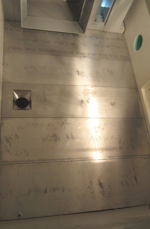
The sheet metal panel covering the NHC/SHC feedthrough port was removed today using a slide-hammer to pull out the concrete anchors (this oversized panel would have interfered with the NHC partition wall). 50cpm was found on the inside of the panel, 100cpm on the NHC side lip of the feedthrough, and 350cpm on the face of the shielding bricks in the feedthrough. Various dimensional measurements of the feedthrough were taken which will be added to the partition wall Solidworks model (IRH1609). The panel was bagged for disposal and a temporary 20"x20" panel was put over the feedthrough and secured with duct tape. A permanent panel with anchored supports that is compatible with the NHC partition wall will be designed and installed at a later date. A swipe of the NHC walls and floor picked up 30cpm after completion of the job. |
|
Tuesday, November 08, 2016, 14:04, Isaac Earle, North Hot-Cell, Development, , , Interference check with TCS turbo pump and proposed NHC duct routing
|
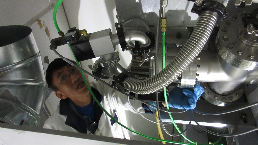
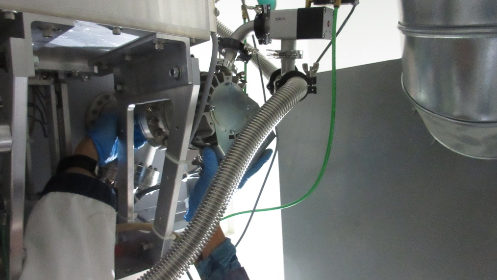
David Wang and I accessed the NHC today to check if the proposed duct routing (IRH1618) will interfere with servicing or replacement of the TCS turbo pump. A piece of plywood was placed in the future position of the NHC/TCS partition wall (IRH1609), and a ducting elbow was placed at the approximate position of the nearest elbow to the turbo pump.
David concluded that the ducting in the proposed location will not have any significant effect on replacement of the turbo pump, and he does not expect replacement will be difficult to perform after installation of the wall and NHC ducting. Standing at floor level towards the east side of the TCS space and reaching upwards seemed to be the best way to reach the turbo pump flange bolts. It was also noted that there was sufficient room in the TCS space for two workers to be in the area.
|
|
Friday, December 09, 2016, 14:58, Isaac Earle, North Hot-Cell, Development, , , NHC service area floor and top of roof block painted
|
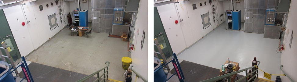
The concrete floor in the North Hot Cell service area and the top of the NHC roof block in the target hall have been painted with Macropoxy 646 oil based epoxy paint, colour Flint Grey. Two coats were used for the NHC roof, and one for the service area floor.
|
|
Tuesday, January 17, 2017, 13:45, Isaac Earle, North Hot-Cell, Development, , , NHC ducting installed
|
The new ducting section connecting the existing duct termination in the TCS space to the NHC partition wall has been installed by Smith Sheet Metal contractors. The installation drawing is IRH1618. There was not enough clearance between the duct pipe and the TCS vessel to butt weld the new ductwork as originally intended. Instead a flange was welded to the existing pipe and also to the new section and the two were bolted together. Drawings of the modifications have been provided by the contractor, and as-built drawings will be completed at a later date. There was not time for the contractor to fabricate a gasket for the flanged joint, so one will be installed by TRIUMF at a later date and included in the as-built drawing package. |
|
Wednesday, January 18, 2017, 11:53, Isaac Earle, North Hot-Cell, Development, , , NHC partition wall installation complete
|
The final panels of the partition wall were installed today as per drawing IRH1609. Sealing, finishing, and painting of the NHC walls and floor can now commence.
|
|
Tuesday, February 07, 2017, 15:57, Isaac Earle, North Hot-Cell, Development, , , Ventilation Ducting Gasket Installed
|
Lead gasket IRH1633 was installed today according to assembly drawing IRH1618 Rev B. |
|
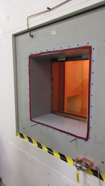
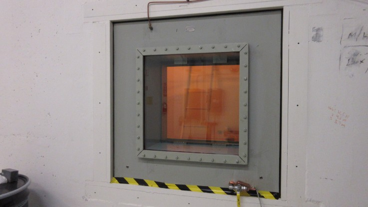
Thursday, February 09, 2017, 14:07, Isaac Earle, North Hot-Cell, Development, , , North Hot Cell Shielding Window Gaskets Changed 23x
|
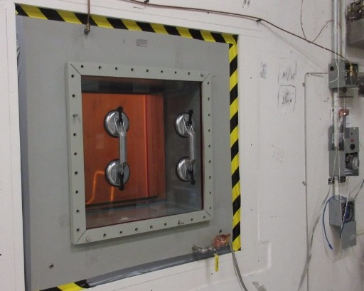
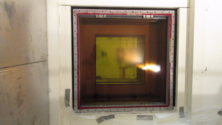
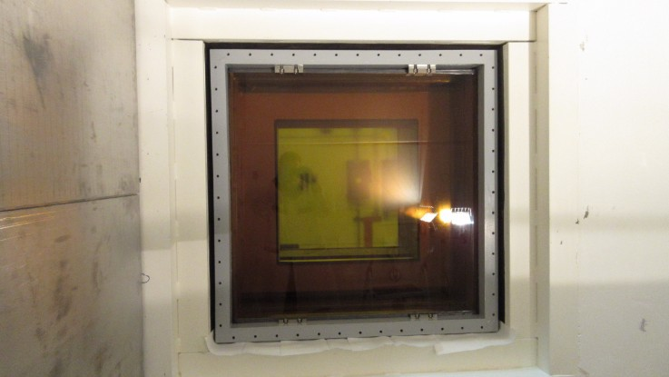
The North Hot Cell shielding window gaskets have been changed and the window has been filled with new oil. Although there was no noticeable oil leaks before starting the job, the gaskets had not been changed since initial installation approximately 15 years ago, so they were done now as part of construction of the new cell. The work took place between January 26 – Feb 8, 2017 following the attached PDF “Full procedure for NHC shielding window gasket change” which references “Gasket change procedure from Hot Cell Services” (also attached).
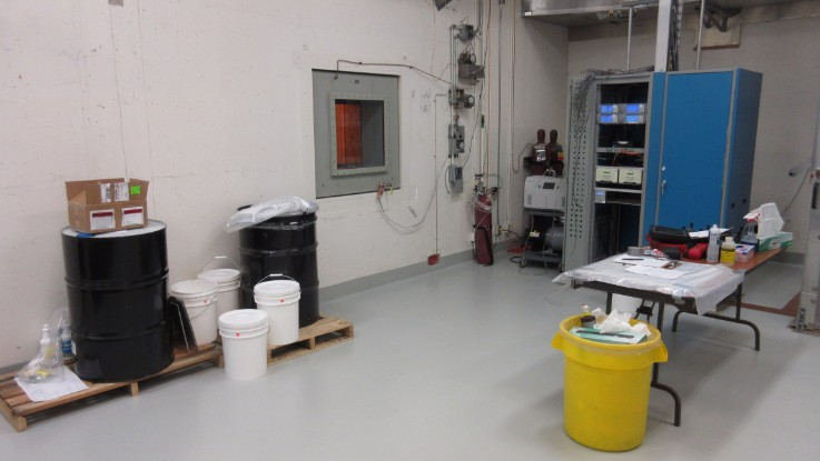
To drain the window a 1/2”polyethylene hose was attached to the drain line using a Swagelok fitting and routed into a 55 gallon drum. A vent valve on the expansion tank was opened to allow air to enter the window. It took approximately 5 hours to drain the window using this method. Approximately 50 US gallons were drained from the window, agreeing with the amount specified on Hot Cell Services drawing #96173-100 (attached).
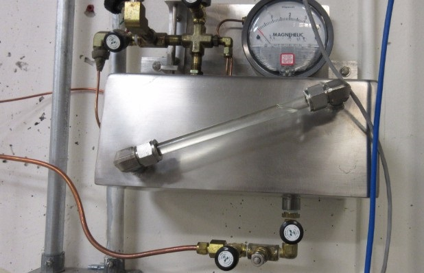
After draining, the window was purged with helium then pressurized to approximately 13” WC with helium. A pressure drop of 0.6” WC was observed over a 2 hour period. While pressurized, a Varian G8601-60001 leak detector was used to sniff for helium around the perimeter of the gaskets on both the hot and cold sides – no helium leaks detected. A small leak was found on the pressure gauge used to monitor helium pressure.
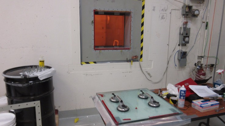
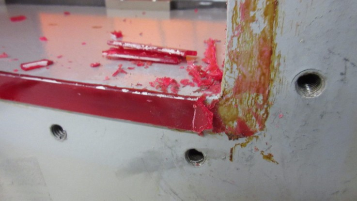
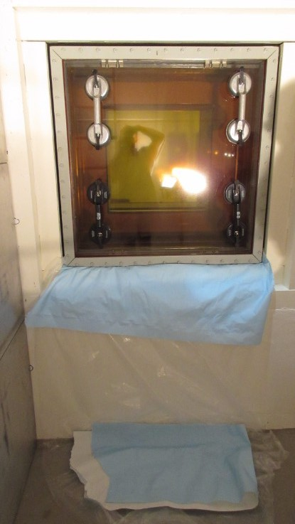
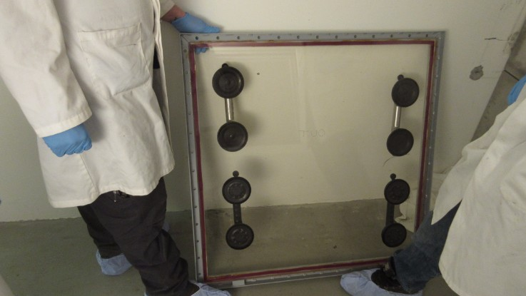
The cold side cover panel assembly was then removed following the HCS procedure. From HCS Drawing #96173-100, the weight of the cold side glass cover panel was estimated to be approximately 50lbs. The guide pins used were McMaster-Carr PN# 93460A385. The trim frame could be easily removed, however the glass panel was stuck to the window housing. A putty knife and isopropyl alcohol were used to cut through the gasket to separate the window from the housing. The alcohol did not damage the paint of the housing – acetone was also tested on a small area and did not cause damage to the paint. Two suction cup handles were used to transport the glass panel, and it was easily lifted by two people. Various methods were attempted to remove old gasket material and gasket adhesive from the trim frame and housing surfaces – the most successful was using a razor blade scraper to remove the majority of the material, followed by an acetone wipe to remove the remainder of the stuck-on gasket adhesive. The panel was reinstalled with new gaskets following the attached procedures - no issues encountered. After torqueing the trim frame bolts the window was leak checked as before. A drop of 0.8” WC was observed over two hours, and no helium could be detected around the perimeter of the new cold side gasket.
The hot side cover panel assembly was changed using the same method as for the cold side. The glass panel was estimated to be 150lbs. A small amount of oil (< 0.5 L) remained behind the hot side glass panel after draining which spilled out after removal of the glass. Four suction cup handles were used, and four people were required to remove and reinstall the panel. After installation the leak check was repeated with a drop of 0.3” WC observed over two hours, and no helium detectable around the perimeter of the hot side gasket.
The replacement gaskets were ordered from Hot Cell Services under PO# 3033973 matching the material and sizes specified on HCS drawing #96173-100.
The window was filled with Drakeol 10B LT MIN OIL NF, Product code: PEN1550-00-C-DR, PO #3034657. The window was filled by lifting the drum onto the walkway leading to the target hall entrance, and siphoning the oil out of the drum with a 1/2” polyethylene tube connected to the drain fitting, and an air vent open on the expansion tank. Oil was added until the expansion tank was approximately 80% full.
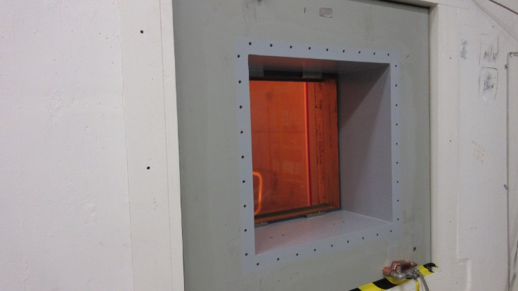
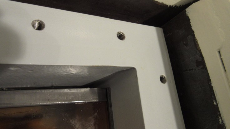
After filling was complete, the cold side housing was repainted using Macropoxy 646 epoxy paint, 4019 Flint Gray. When the inside of the NHC is next accessible the hot side trim frame bolts will be re-painted to protect the bare metal exposed from removing and reinstalling them.
Note that a quote for $74,313 ($56,823 USD) (PDF attached) was received from Hot Cell Services for them to do this job. We were able to successfully complete this ourselves with approximately $4500 required for the gaskets, $200 for other materials, and roughly 8 FTE days of work.

|
|
Friday, February 24, 2017, 15:12, Isaac Earle, North Hot-Cell, Development, , , NHC interior walls/floor/ceiling re-finished, sealed, and painted 8x
|
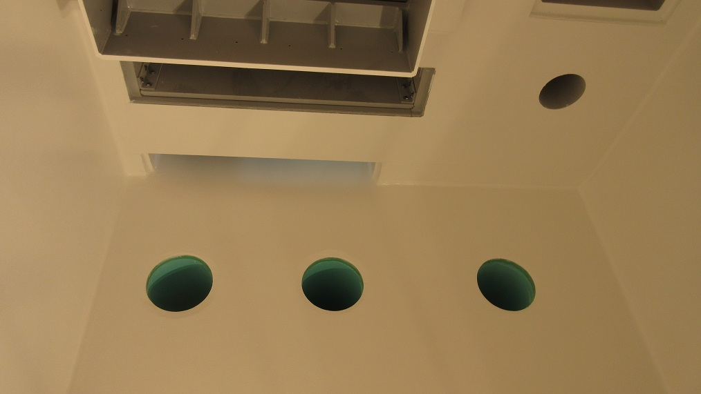
The North Hot Cell interior walls, floor, and ceiling were re-finished, sealed, and painted by Omni Coating from Feb 6 - 17 under PO #3036471. This job required 2-3 people for 4-6 hours per day over the 2 week period. First the existing surfaces were ground and/or sanded to remove existing coatings and protrusions/sharp edges. This was followed by a coat of primer to highlight uneven surfaces and improve adhesion of following fillers and coatings. Metal shims between the cell walls and roof were cut away where they protruded into the cell. Loose steel cylinders between SHC and NHC spaces were fixed in place using epoxy filler. Epoxy or polyurethane fillers were used to fill all gaps, cracks, holes, etc, as detailed below. Foam backer rod and polyurethane filler were used to seal all large wall-to-wall and ceiling-to-wall gaps. An approximate 2cm radius rounded corner was formed at all wall-to-wall and floor-to-wall corners using polyurethane sealant. The interior of the tool-port, personnel access hatch, as well as the north roof hatch were also re-finished with the same procedure. After all sealing and finishing work the surfaces were coated with "Mill White" Macropoxy 646 Fast Cure Epoxy Paint as per manufacturer instructions. Note: this paint is recommended by the manufacturer for nuclear applications and has been tested for decontaminability: 99% water wash; 95% overall as per ASTM D4256/ANSI N 5.12 as well as for radiation tolerance: Passed ASTM D4082 / ANSI 5.12 with a 525 micron thick coating.
The following products were used as described (data sheets attached):
Sanitile 120 Universal Acrylic Primer - 50-75 micron dry film thickness coat applied over all existing ceiling, walls, and floor surfaces after preparation by sanding
Sika Duochem 8107 Epoxy Paste - Used for filling voids and cracks in concrete surfaces
Sikaflex 291 Polyurethane Elastomeric Adhesive and Sealant - used for caulking joints and cracks in the concrete walls and aluminum panel wall and for creating radiused corners in wall-to-wall and wall-to-floor corners
Macropoxy 646 Fast Cure Epoxy Paint - 4 coats applied on all surfaces using rollers or brushes to create a total thickness of 525 microns as per data sheet

|
|
Tuesday, February 28, 2017, 17:51, Isaac Earle, North Hot-Cell, Development, , , NHC flanged ducting connection sealed
|
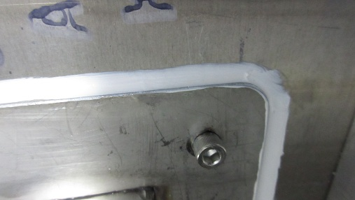
The North Hot Cell ducting (IRH1617) has been sealed with a bead of Sikaflex 1a polyurethane construction sealant where the flanged connection bolts to the NHC/TCS partition wall. When this sealant shows signs of aging it may be cut away and re-applied without unbolting the flange.
|
|