| ID |
Date |
Author |
Category |
Type |
Module |
Target/Number |
Subject |
|
1687
|
Wednesday, February 14, 2018, 10:06 |
Anders Mjos | ITW | Maintenance | TM2 | | Replaced parker couplings on Window cooling line |
By Anders & David. Couplings will be taken apart for inspection. |
|
1688
|
Friday, February 16, 2018, 13:46 |
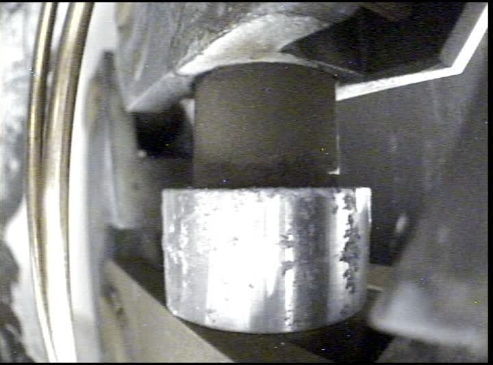
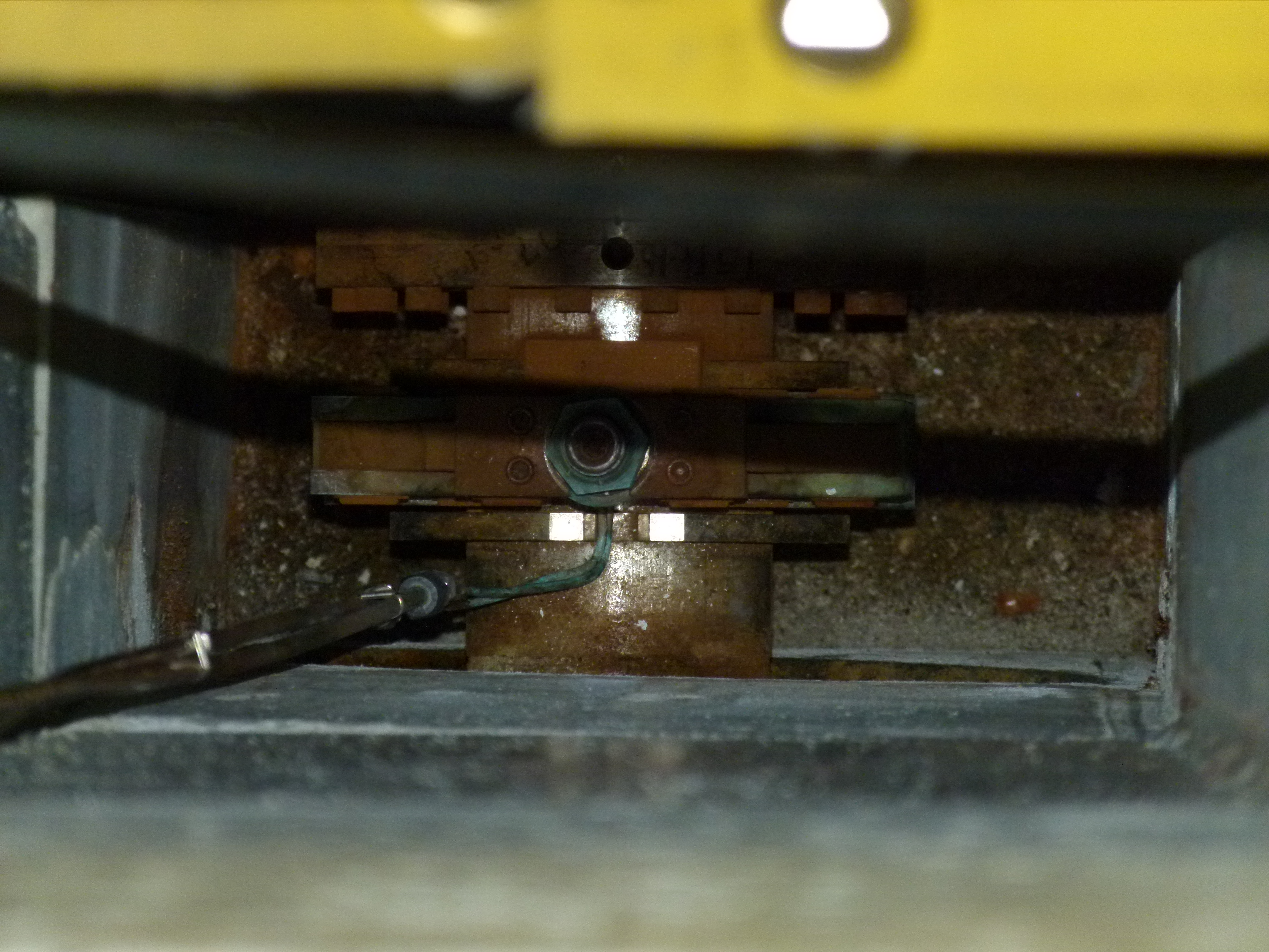
Anders Mjos | ITW | Maintenance | TM2 | | Parker coupling inspection |
Findings and photos from the inspections attached. The inspection was conducted by Anders, David and Maico. |
|
1689
|
Wednesday, February 28, 2018, 14:47 |
David Wang | ITE | Standard Operation | | | leak check ITE primary and secondary vacuum vessel. |
2018-02-27: Anders and I finished leak check on ITE primary and second vacuum vessel seals. LD connected to ITE BV2 valves between. LD, Base Leak rate 1.2 xE-9atm.cc/sec, base pressure 0.0XE-4torr. There is a leak has been found on TM4 service cap KF25 blank off. The o-ring on the blank off will be changed later. It is an easy fix . Other seals are good. The big T tank seal on secondary vessel is leak checked as well. It is still fine. Helium pressure on TM4 water lines will be fulfilled at TCS to save dose.
2018-02-28 Leak checked ITW today, LD connected to ITW BV2 valves between LD base LR0.0XE-9 atm.cc/sec. base pressure 0.0Xe-4torr. There is leak has been found on exit module 1 service cap on topcover plate o-ring. The leak is located on the south side of east edge on exit 1. This is the side module 2 is close beside. The leak rate is up to middle of E-8atm.cc/sec range with 1-2 second helium spray. The leak and leak position are double checked and confirmed. To completely fix this leak, the o-ring for top cover plate need to be replaced on service cap.It will be a major shut down job. The leak is close to ITW TP3 so it is less affect on beam line elevation vacuum. Vacuum group experts will be consulted to see if we could leave it to next year shutdown. Other seals are good including big T-tank seal on secondary vessel. TM2 source tray will be replaced this yea rso no helium pressure test on water lines is needed at this moment. |
|
1691
|
Tuesday, March 06, 2018, 09:53 |
David Wang | ITW | Standard Operation | TM2 | | Tm2 and Tm4 vacuum disconnection |
The job is done. See attachment. |
|
1692
|
Wednesday, March 07, 2018, 10:18 |
David Wang | ITW | Standard Operation | | | Oil leak on target station vacuum primary back pump. |
I can not see oil in sight window of the primary pump during visual inspection. The aluminum tray underneath the pump is filled with oil. The performance on this pump start to drop by watching ITH CG4 reading. A fault report with suggestion is issued to vacuum group. Everything on secondary pump looks fine. |
|
1693
|
Wednesday, March 07, 2018, 10:36 |
David Wang | ITE/ITW Cooling | Development | | | HALCW resin can flow meter replacment |
HALCW resin can flow meter replacement is done. Less that 100 mL water was drained to a small tray during the job. RPG checked the water. Less than 20 counts. Water are dumped the high active sump. The HALCW MP1 is started. No leak on new gauges and fittings. Old gauge is labeled , bagged, and stored in TH. |
|
1694
|
Thursday, March 08, 2018, 14:10 |
David Wang | ITW | Maintenance | | | Two small water leak has been found in ITW. |
Two small water leaks have been found on ITW High active water system. One is from an unused 1/4" copper valve stem. another is on supply 1.5" supply line valve body top sealing. Both of them are seeping water from seal. 1/4" copper valve will be replaced with a new one. 1.5" supply line valve will be replaced by an old valve with all new seals. I have all spare parts in hand. At present, water supply to ITW are stooped to reduce leak rate. Two aluminum flat tray are put underneath leak valves to hold small amount leak water. Both leak will be fixed in April mostly. |
|
1696
|
Thursday, April 05, 2018, 11:29 |
David Wang | ITW | Maintenance | | | ITH MP1 replacement |
ITH MP1 is replaced today with a new style pump.The new pump is 0.75 inch higher than old pump on inlet and exhaust so a new solid inlet adapter (KF50-25) has to been used. For future secondary pump ITH MP1S replacement, we need a new adapter 0.75 inches shorter as well. The new pumps is started . Everything works fine. Old pumps is drained , bagged, and stored in TH B2 level. All radioactive garbage produced during the job are bagged , tagged, and stored in TH as well. |
|
1697
|
Monday, April 09, 2018, 06:36 |
David Wang | ITW | Standard Operation | | | ITW Turbo -pumps switch off |
I asked MCR to switch off ITW TP3,4 TP1s,2s this morning. |
|
1701
|
Tuesday, April 17, 2018, 11:05 |
David Wang | ITW | Repair | | | Disconnect ITW entrance module |
ITW entrance module has been disconnected. All connections are labelled before or during disconnection. The 24VDC electrical plug on ITW TP1S is broken . It will be replaced with a new plug. The lift yoke is installed onto module without difficulty. |
|
1702
|
Thursday, April 19, 2018, 10:27 |
Travis Cave | ITW | Maintenance | | | Entrance module move |
The west entrance module has been moved from the west target station to the silo. |
|
1703
|
Friday, April 20, 2018, 15:33 |
Keith C Ng | ITW | Repair | | | ITW beam tube repair job |
2A2 window has been removed from ITW and beamlines has removed the beamtube from the penetration. The penetration has been sealed with plastic sheeting and duct tape to maintain the ventilation depression between the 2A tunnel and the Target Pit.
Window is currently stored in a lead flask in the target hall. Window fields are 26 mSv/h OC, 1.2 mSv/h at .5m. There is a 10 uSv/h field outside the flask with the window inside it.
Clamp is currently sitting bagged in ITW Station Pit, it is quite corroded.
Tank flange was video inspected but still needs to be cleaned, currently there is a slip on dust cover over the flange to protect it.
Work will resume after the nuclear ventilation comissioning is completed.
|
|
1704
|
Friday, April 27, 2018, 15:06 |
Keith C Ng | ITW | Repair | | | ITW beam tube repair |
Vacuumed out remainder of debris from the wall penetration, removed cradle and checked condition. Down stream support bracket sees advanced stages of material loss (OBO 20-30% loss). See attached photos.
RPG reports that the removed beam tube has 15k CPM on the interior of the beam tube.
Tank flange was cleaned as per 2009 repair report, looks OK. Video capture of flange inspection attached as .zip file.
.03" shim was inserted into the clamp indexing block.
|
|
1705
|
Tuesday, May 01, 2018, 10:54 |
Keith C Ng | ITW | Repair | | | 2a2 window installation and beamtube repair |
Yesterday we installed the 2a2 window, the drive screw was torqued until 70 ft-lbs and we stopped, the yoke is not fully closed to its hard stop with roughly 7/8" to 3/4" still to go. Similar to identical conditions to 2a3 beamline window install, see https://elog.triumf.ca/TIS/RH-ISAC/647 for that install. Otherwise clamp looks centered and installed correctly.
Concerns with the cooling lines for the window WRT to the base of the shielding plug: There is no jog bend indicated on drawings for the transition of the window cooling lines from beamline center to the corner of the shield plug penetration. See photo for cooling line position on initial removal of shielding plug. It was decided to not add a jog for the shield plug and to carefully reinsert it being mindful of the cooling lines. The shielding plug has a chamfer on the corner to allow the cooling lines to be routed to the top.
A new beam tube cradle is being manufactured where the old one will removed and the new one swapped with the beam tube in situ. Both sides of the window still need to be leak checked. |
|
1709
|
Thursday, May 03, 2018, 13:26 |
Anders Mjos | South Hot-Cell | Repair | TM4 | | EZL short troubleshooting |
Yesterday Aaron, Isaac and Anders inspected the EZL connection from the service chase to the optics tray using the goose neck camera in SHC. No issues or shorts could be identified. Containment box was not removed.
Today David and Anders opened up two panels on the service cap and inspected the EZL connection. No issues or shorts could be identified. Photos available on DocuShare.
Next step will likely be to remove the containment box and inspect the optics tray. |
|
1710
|
Friday, May 04, 2018, 11:21 |
David Wang | ITW | Repair | | | 2A2 winodw leak check in TH |
Anders and I leak checked new 2A2 window seal on ITW side. Leak detector was connected to ITW TP4. Base leak rate 0.0Xe-9 atm.cc/sec. base pressure 0.0xe-4 torr. Sprayed 15-20 psi directly underneath 2A2 window by using exist 2a2 window leak check copper tube. The leak detector got response in 5 seconds when helium was applied. the leak rate was 5xe-6 atm.cc/sec. Once the helium source was closed, the leak rate dropped quickly back to base level. To confirm the leak is at window , I sprayed 15 psi helium around all top flange seals of TM and entrance module. There was no direct response during the spray( about 1.5- 2 minutes). There was a weak slow up response (up to 1.0 xe-7 atm.cc/sec) which was started after 1.5 minutes of spray. The weak response is cause by helium drift in my view. Our conclusion is the 2A2 window seal on ITW side is not perfectly sealed. The elak we saw on LD is ture , and it is located on window. The station will be vented soon for shielding plug moving back. . |
|
1711
|
Friday, May 04, 2018, 15:46 |
Anders Mjos | South Hot-Cell | Repair | TM4 | | EZL short troubleshooting |
| Anders Mjos wrote: |
|
Yesterday Aaron, Isaac and Anders inspected the EZL connection from the service chase to the optics tray using the goose neck camera in SHC. No issues or shorts could be identified. Containment box was not removed.
Today David and Anders opened up two panels on the service cap and inspected the EZL connection. No issues or shorts could be identified. Photos available on DocuShare.
Next step will likely be to remove the containment box and inspect the optics tray.
|
The containment box was removed yesterday. One of the main insulators on the source tray had cracked at the rear close to the bolt to the source tray mounting plate (see photos using link above)
Troubleshooting continued this morning with disconnection of the optics tray from the module. The banana plug copper tube connection was removed form the optics tray side. With the connection removed, the measurement showed open line on top of the module indicating that the problem is on the optics tray |
|
1712
|
Wednesday, May 09, 2018, 08:48 |
David Wang | ITW | Repair | | | 2A2 winodw leak check on ITW vacuum vessel. |
Leak detector is connected to ITW TP4. LD Base leak rate 0.0XE-09 atm.cc/sec. Helium line is connected to existing window leak check 1/8 " copper tube. Applied 18psi helium for 1 minute. No response on LD. The window seal is good on ITW vacuum vessel. |
|
1714
|
Tuesday, May 15, 2018, 10:21 |
David Wang | Conditioning Station | Standard Operation | TM4 | | Tm4 water circles helium pressur test result |
Helium pressure test on TM4 water lines is done this morning. 70 psi helim , 1 minutes time to each circle. The result:
A(oven+): 0.00xE-9 atm.cc/sec
B(Oven -): 8.1Xe-7 atm.cc/sec
C(tube -): 0.00xE-9 atm.cc/sec
D(tube+): 1.0xE-5 atm.cc/sec
PQ(coil 2): capped on top. water lines were removed because of leak
RU(Coil1): 0.00xE-9 atm.cc/sec
EE: 0.00xE-9 atm.cc/sec
MSP: 0.00xE-9 atm.cc/sec
HS: No target, capped on top. It was fine on last target check in 2017 Oct.
window: Capped on top. Containment box is not installed.
The leak check on D line caused the IG1 small response during test.
B and D circle are double checked. The reasults are same.
D line leak is in E-5 atm.cc/sec range. It is possible to locate it by using helium spray method in SHC. The containment box is not on so it should be easy to do it.
Switch on IGA gauge at TCS and apply helium and water at certain psi to check the IGA response may give us more information on these leaks.
All lines were test in last year shut down. They were good.
|
|
1715
|
Thursday, May 17, 2018, 11:30 |
Anders Mjos | Conditioning Station | Maintenance | TM4 | | HV test/conditioning of damaged source tray |
BIAS only. Water lines looped on top. Containment box off.
Thursday, May 17, 2018, 11:20: Vacuum 7.2E-7 Torr
Thursday, May 17, 2018, 11:30: 10 kV
Thursday, May 17, 2018, 11:42: 20 kV
Thursday, May 17, 2018, 12:14: 25 kV
Thursday, May 17, 2018, 12:35: 30 kV
Thursday, May 17, 2018, 16:13: 35 kV
Thursday, May 17, 2018, 17:339: 37.5 kV
Thursday, May 17, 2018, 17:40: vacuum 6.8E-7 Torr
Thursday, May 17, 2018, 18:13: BIAS off. |