 Monday, July 23, 2012, 16:01, Isaac Earle, Development, Target 1, Target, Target Flask Seismic Restraint Clamps Installed Monday, July 23, 2012, 16:01, Isaac Earle, Development, Target 1, Target, Target Flask Seismic Restraint Clamps Installed 
|
Installation of the seismic restraint clamps has been completed for the MK1 and MK2 target flasks in the Remote Handling lab (photos attached). Two clamps on the MK1 flask required 3/8" shims due to warpage of the flask baseplate (see photo IMG_0429).
Dragan Mitrovic has been notified so that he can inspect the installation and close the work request. |
|
Friday, April 12, 2013, 17:33, Isaac Earle, Development, Target 1, Cooling, T1 & T2 high-temp limit switch installation, wiring, and commissioning complete
|
Installation, wiring, and commissioning of the high temperature limit switches for the T1 and T2 cooling packages was completed today as part of SAS project SASP0120. The relay output from the switches was wired in series with the Central Safety System signals for T1 and T2 (cable number 13250 and 12250 respectively) in break-out panel #2 on the Meson Hall south mezzanine. There were already 3 other circuits wired in series with each signal for various other interlock requirements.
After wiring, commissioning of the switches was performed according to the following procedure:
- With the limit switches in a non-tripped state, it was confirmed that the safety signals were reaching the CSS in the main control room as expected (had to jumper T2 circuit to achieve this as the T2 target is not currently installed)
- The limit switch was tripped by adjusting the set point on the switch, it was confirmed that the signal was lost
- The set point was changed to a non-trip level, and the switch trip cleared, confirmed that the signal in MCR returned
- The enable signal from each cooling package was removed by shutting off the cooling package (for T2 just removed jumper), confirmed that safety signal lost as expected
- Reversed this condition and confirmed that the signal returned
- Checked that the thermocouples are performing properly, and the switches actually trip on high temperature by directly applying heat to the thermocouple area on the cooling package using a heat gun; the switches tripped as expected when the set-points were exceeded
The results were discussed with John Drozdoff (Safety Systems group leader) who approved the method.
The final task remaining for SASP0120 is to route the PRV outlets to the 1A tunnel active drain using flexible hosing.
|
|
Friday, April 19, 2013, 09:55, Isaac Earle, Development, Target 1, Cooling, T1&T2 cooling package safety/standards compliance upgrade complete (SASP0120)
|
Yesterday (April 18th) the T1 and T2 cooling package PRV outlet lines were routed to the active drain in the 1A tunnel. All items for the safety and standards compliance upgrade for T1 and T2 as specified in Document-68861 are now complete. |
|
Tuesday, May 14, 2013, 13:26, Isaac Earle, Development, Target 1, Target, T1 & T2 Profile Scan
|
The T1 and T2 profile monitors were used during today's development shift. Target ladder movement for T1 was done at the panel on the mezzanine, for T2 the portable control box was used. Both monitors actuated properly and the scans did not show any "missing" wires. The profiles at both targets were found to be too broad and were adjusted to span 2 wires horizontally and 6-7 wires vertically (Yi-Nong Rao). |
|
Wednesday, October 23, 2013, 15:30, Isaac Earle, Development, Target 1, Cooling, T1 & T2 High Temp Safety Switch Tested
|
An end-to-end test was performed on the new T1 and T2 high temperature safety switches yesterday during the maintenance day. The switch set points were lowered below the current temperature and it was confirmed that all warning messages and XTPAGE status changes occurred as expected. |
|
Tuesday, March 25, 2014, 18:24, Isaac Earle, Development, Target 2, Water Leak, Water Detecting Sensor Install at T1 & T2 9x
|
Water detecting strips were installed around the T1 and T2 areas today with Doug Preddy and contractors from SMT Research. Four sensors were installed at various locations on each cooling package. Four sensors were installed on the top surface of the T2 monolith. In addition, four sensors were routed for future installation at the T1 monolith (it is currently covered by blocks and requires cleaning and painting before sensor installation).
See the attached PDF for sensor ID numbers and placement specifics.
Photos are attached of the sensors installed around the T2 monolith and cooling package. |
|
Wednesday, May 14, 2014, 20:36, Grant Minor, Development, Target 2, Target, Target exercised to position 0, then back to 2.0 mm above position 4
|
The T2 target was exercised to position 0 around 6:15pm so that the T2 profile monitor could be used by operations. The T2 water package was re-enabled when the target was in position 0, however this resulted in some trips of the cooling package.
Operations called around 7:45 to request return of the target to about 2mm above position 4.
The target position was re-set so that the position reading fluctuated roughly between 2.7 and 1.6 mm above position 4 (hovering roughly around 2.0 mm), and so the potentiometer reading was hovering roughly between 0.801 and 0.798.
The cooling package was re-started, and called operations to confirm the system was OK. |
|
Monday, November 17, 2014, 10:14, Isaac Earle, Development, Target 1, Active Sump, Filter Installed Downstream of RH HC Lab Active Sump
|
A filter housing and filter were installed by Dan McDonald on November 14 in the piping section between the Remote Handling Hot Cell Lab active sump and the city sewer drain as shown in the attached picture. The purpose of the new filter is to prevent pieces of active material from being released to the drain when the sump is pumped out. If small pieces of active material enter the sump they may sink to the bottom, and not be captured in a water sample which is taken from the top of the sump.
The filter housing is a Waterite HP1034CLUR-KIT, and the installed filter is a 10" Cuno Microwynd 25micron filter.
This modification was approved by Curtis Ballard, Joe Mildenberg, and Grant Minor prior to installation. |
|
Friday, February 27, 2015, 18:06, Isaac Earle, Development, Target 1, Target, T1 Rotary Collimator Water and Air Line Investigation
|
Ron Kuramoto, Keith Ng, John McKinnon, and myself spent some time today investigating water and air lines related to the T1 Rotary Collimator (Col. A). We discovered the following:
- There is a panel on the back (south) side of the T1 cooling package with 3 air lines for Col. A actuation, Col A cooling water supply & return, and the Col. Shield water cooling supply and return
- The air lines coming from the panel were decomissioned in 2003 by Tom Lyth, and at least 2 out of 3 were replaced with CuALCW water from the M13 header in the BL1A tunnel
- Motion / actuation of the rotary collimator was disabled in Oct 1994 and it is now used only in one position
- The two water lines coming from the M13 header (which connect to the actuation cylinder) will be disconnected, capped, and tagged. The M13 header can then be completely removed
- It is suspected, but not yet 100% confirmed that Col. A and the Collimator Shield are still cooled by the lines passing through the panel at the back of the cooling package
- A flow test will be performed to confirm this, which will also confirm that the Q4 flow meter at the cooling package measures cooling water flow to Col. A |
|
Thursday, April 09, 2015, 13:56, Isaac Earle, Development, Target 2, Target, T2-MK2 target wired for version identification, cable ties replaced, ready for use
|
The "POT/CAM" MS connector on the T2-MK2 has been wired to allow automatic target version number identification by the new T1/T2 control system. Pin A was jumpered to Pin C. (MK1 targets will use Pin A to Pin B jumper).
The nylon cable ties on the target assembly were found to be very brittle and fragile, they have been replaced with PEEK cable ties.
The T2-MK2 target is now ready to be moved to the beamline. |
|
Wednesday, April 22, 2015, 09:46, Isaac Earle, Development, Target 1, Target, Water Sensors Installed on T1 Monolith
|
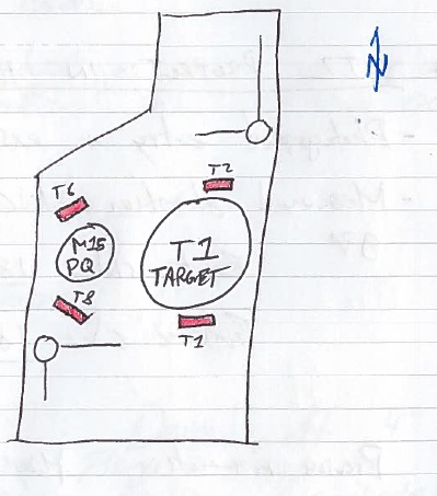
Four water sensors have been installed on top of the T1 monolith. These water sensors were wired and brought to the area during the 2014 shutdown, but installation was delayed so that the top of the monolith could be painted first. The sensor labels (attached to the sensor cable) are: T1, T2, T6, and T8. The location of each sensor is documented on the diagram below. Two photos of the top of the monolith are also attached. Doug Preddy has been notified.
|
|
Wednesday, April 22, 2015, 15:17, Isaac Earle, Development, Target 1, Target, T1-MK2 wired for version identification
|
The T1-MK2 target was wired for automatic target version detection by the new PLC control system (A to C jumper in POT/CAM MS connector). T1-MK1 and T2-MK1 targets still need to be wired which can take place after the shutdown without moving them from the storage pit. |
|
Thursday, April 23, 2015, 13:40, Isaac Earle, Development, Target 2, Other, T2 Protect Monitor Elevation Adjustment
|
- T2 Protect Monitor moved from the beam line to the hot cell on Monday April 20th
- Elevation of the plate center measured at 1839.0mm from the base of the vacuum flange
- Old monitor cassette photographed (attached). Heat mark noticed on exit side approximately 10mm above and 5mm south of plate centers (cause unknown, and no matching mark on entrance side)
- Old monitor cassette removed, new one installed. New elevation 1836.1mm (2.9mm upward shift - 3.0mm was requested)
- Electrical check performed by Probes Group on April 22 - They reported that it looks normal
- T2 Protect Monitor returned to the beamline April 22 in the evening. Cables plugged in and flange bolts installed
- Vacuum pumped down normally on April 23 in the morning
- Probes group repeated the electrical check after installation from the 1A mezzanine - They reported that it looks normal
- The old monitor cassette will be left in the hot cell for possible future use |
|
Tuesday, April 28, 2015, 15:55, Isaac Earle, Development, Target 1, Target, Target Version Jumper Wires Installed for T1-MK1 and T2-MK1
|
The T1-MK1 and T2-MK1 targets have been re-wired to allow version identification. Work was performed in the target storage pit. Approximate field around the targets in the pit was 100microSv/hr. Disposable coveralls were worn for the job and had 800cpm of contamination on completion. All nylon cable ties on the targets were replaced with PEEK cable ties. Total dose received was 0.06mSv by Isaac Earle. This modification has now been completed for all T1 and T2 target assemblies. |
|
Thursday, June 11, 2015, 16:59, Isaac Earle, Development, Other, Controls, Lab Test of New T1/T2 Level Sensors
|
The new T1/T2 level sensors (Omega LVCN414) were tested in the RH HC lab today using the Omega software on a laptop and positioning the level sensor flange above a bucket of water with similar height as the expansion tank.
The level sensors behaved as expected with varying water level.
The level sensor was configured with the following parameters:
- Loop Fail-Safe: Empty
- Output at Empty: 4mA at Bottom
- Start-up condition: Empty
- Sensor Height: 50.1cm (Based on TBP1682)
- Fill Height: 45.0cm (Based on TBP1682)
This results in 4mA output at 0cm tank height, and 20mA output at 45.0cm tank height.
This test will be repeated next week with the sensor wired directly to the PLC. |
|
Friday, June 19, 2015, 17:11, Isaac Earle, Development, Other, Controls, PLC Test of Ultrasonic Level Sensor
|
The new T1/T2 level sensors (Omega LVCN414) were hooked up to the PLC and the test performed on June 11 was repeated.
The water level above the base of the bucket was measured using a tape measure, as well as with the level sensor at various intervals as the bucket was filled and then drained:
Tape Measure Level (cm) --- Reading from Ultrasonic Level Sensor (cm)
Empty --- 0
3.3 --- 3.3
6.7 --- 6.7
12.2 --- 12.2
20.5 --- 20.3
29.2 --- 28.5
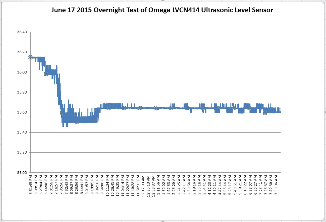
36.6 --- 36.3 (Last measurement on June 17, left overnight, see graph below)
36.6 --- 35.6 (First measurement on June 18)
31.3 --- 30.2
22.0 --- 21.9
13.1 --- 12.3
7.3 --- 6.5
Empty --- 0
Data was recorded while the sensor was left overnight (see attached plot). After approximately 2 hours, the sensor stabilized and then fluctuated less than 0.1cm for the next 12 hours. Overall these tests proved that this sensor will be suitable for the intended application and the parameters used for configuration are appropriate.
|
|
Wednesday, July 08, 2015, 16:21, Isaac Earle, Development, Target 1, Target, 0.003" 347 SS Sheet for T1/T2 Targets Received
|
A 5lb roll of 347SS sheet was received today. This alloy is to be used for the target windows of the new T1 and T2 beryllium target cassettes that will be manufactured in the near future. The material was ordered from Alloys International (PO# TR206407). A mill spec report was included with the material, a scanned copy is attached in PDF format. The roll will be stored in the meson hall RH hot cell lab office on the shelving above the work bench. |
|
Thursday, July 09, 2015, 13:51, Isaac Earle, Development, Other, Target, New T1 and T2 Beryllium Targets Ordered
|
An order for new T1 and T2 beryllium targets was submitted to the TRIUMF machine shop today. A total of seven T2 targets and twleve T1 targets were ordered to match existing stock of wire EDM target shells. All required materials were supplied. Completion by October 30, 2015 was requested.
A complete set of new drawings for both targets were released in June 2015 (TBP1683 for 12mm T1 Be target; TBP1691 for 10cm T2 Be target)
Current target stock for T1 (12mm Be) includes: 1 target on the shelf, 1 target on the MK1 target assembly (position 4, has not seen beam), 1 target on the MK2 target assembly (position 4, currently in use).
Current target stock for T2 (10cm Be) includes: 1 target on the shelf, 2 targets on the MK1 target assembly (position 3, has seen beam; position 2 has not seen beam), 1 target on the MK2 target assembly (position 4, currently in use). |
|
Friday, July 17, 2015, 10:14, Isaac Earle, Development, Target 1, Target, T1/T2 Be Target Failure History & Replacement Plan
|
T1 and T2 beryllium target failure history was investigated back to 2000 (as far as XSTRIP records were readily available). For each target cassette the following were noted: length of time the target was subject to direct beam, length of time the target was on the ladder w/o direct beam, and method of failure. The purpose of the study was to devise a target replacement strategy so that T1 and T2 beryllium targets are preemptively retired from service to reduce the occurrence of failure while running which causes loss of beam time, extra dose to personnel, and damage to equipment.
The following recommendations are the result of the study:
- T1 beryllium targets should be retired after 9.0 months of running time
- T2 beryllium targets should be retired after 12.0 months of running time
- Multiple targets should be installed on each target ladder (at least 2, possibly 3) so that targets may be switched during a running period if required and less target assembly moves are required
A PDF copy of the Excel spreadsheet is attached which includes target use history, failure history, summary of results, and more specific recommendations for each target assembly. This study and the replacement plan recommendations were reviewed and endorsed by Grant Minor and Yuri Bylinski. This spreadsheet should be reviewed and updated every shutdown period (including Fall mini-shutdowns), as well as anytime there is a target failure.
|
|
Thursday, August 13, 2015, 09:47, Isaac Earle, Development, Other, Other, "Clamp A" disassembled and used to build clamp "TRH1257-#01"
|
The 4" Marman flange clamp (IRH0001) labeled "Clamp A", as used in the testing detailed in Document-114623 Release 1, has been disassembled. The parts were used to build a TRH1257 clamp which uses the new TRH1259 jaw with 0.480" jaw root width. This new clamp has been labeled "TRH1257-#01", and will be tested with Helicoflex H-303654 seals in the near future. |
|