 Thursday, May 02, 2013, 10:09, chad fisher, South Hot-Cell, Repair, TM3, , Service tray water block leak check Thursday, May 02, 2013, 10:09, chad fisher, South Hot-Cell, Repair, TM3, , Service tray water block leak check
|
David and I preformed a helium leak check on the service tray waterblocks and verify that no damage had been done during jig installation. All 14 circuits were checked and verified to be ok except circuit E and circuit I which were unstable when helium was applied. The resonse time on E and I would suggest that it is an issue with the bungs that were used and not the braze joint however. |
|
Friday, March 07, 2025, 09:16, David Wang, Cooling, Maintenance, , , Service of 28 female Parker 1/4 quick connectors in ITW and ITE
|
Service of Parker 1/4 quick connectors in ITW and ITE have been done. all 28 female connectors were serviced. o- rings and valve stem in quick connectors were replaced. the serviced connectors have been installed back to ITW and ITE. Visually inspected all connectors with flowing through them. No leak, and they function well. |
|
Friday, July 05, 2013, 09:22, chad fisher, South Hot-Cell, Repair, TM3, , Service Tray Water Block Inspection
|
I have inspected the service tray water block and suggest that they SHOULD be cleaned/polished before we install the new source tray.
The water blocks have slight water scalling to the inside of the ID of where the c seals locate.
I have taken two close up pictures of each water block for reference and to document their current state. They can be found at http://documents.triumf.ca/docushare/dsweb/View/Collection-10841
|
|
Thursday, February 21, 2019, 15:10, Isaac Earle, Safe Module Parking, Development, , , Seismic requirements for SMP
|
Dragan Mitrovic, TRIUMF structural engineer, was consulted earlier this week regarding seismic requirements for the SMP assembly. Installation location, overall dimensions, total weight, and the center of mass for assembly IRH1670 were provided to him by e-mail. On Feb 20th he communicated verbally that he had analyzed the assembly for seismic loads, and concluded that this equipment does not require anchoring or any other form of seismic restraint.
Update (May 30, 2019): Confirmed with Dragan that the approach he used for analysis was that specified in the BC Building Code (both 2012 edition and updated 2018 edition). |
|
Thursday, October 10, 2024, 12:20, Adam Newsome, Facilities, Standard Operation, , , Safety Walkaround complete - ISAC Hot Cells, Target Hall
|
A safety walkaround was completed for the ISAC Hot Cells and Target Hall Areas.
The resulting spreadsheet can be found on DocuShare as Document-242733.
Main deficiencies identified:
- Hot Cells:
- Phone not working at North hot cell operator station
- Target Hall:
- Uncertain if NHC and SHC ventilation pressure gauges have recently been inspected
Action has been taken on all deficiencies. |
|
Friday, January 03, 2025, 09:59, Adam Newsome, Facilities, Standard Operation, , , Safety Walkaround complete - ISAC Hot Cells, Target Hall
|
A safety walkaround was completed for the ISAC Hot Cells and Target Hall Areas.
The resulting spreadsheet can be found on DocuShare as Document-242733.
Main deficiencies identified:
- Hot Cells:
- NHC right manipulator gripper stuck (known, repair planned)
- Target Hall:
- 50% of overhead light bulbs burnt out (David Wang contacted Electrical Services to rectify)
- One RH camera for target pit not working (Travis Cave notified)
Action has been taken on all deficiencies. |
|
Wednesday, July 17, 2024, 15:06, Adam Newsome, Facilities, Standard Operation, , , Safety Walkaround Complete - SHC/NHC Area
|
A safety walkaround for July 2024 was completed for the B2 level by A. Newsome. No deficiencies to report.
Results can be found in the master spreadsheet |
Thursday, August 06, 2020, 14:33, Adam Newsome, Spent Target Vault, Development, , , Safety Group Relay Interface Installation 
|
A relay contact-based interface module was installed in between Safety Group's storage vault door enable junction box and Remote Handling's control module for the vault door.
The purpose of this module, which contains a diode bridge and relay, is to isolate the safety system from the control module to prevent back-voltage on the safety system which can damage the PLC's power supply.
In the new configuration, rather than receiving a 24 VDC signal from the safety PLC, this signal activates the relay, whose normally closed contacts supply 24 VDC (from internal) to the safety relay inside the control module. Wiring was modified inside the control module to account for this change.
In investing how to achieve the same functionality as before this change, it was determined that the control module's electrical schematic was not correct and did not reflect the actual wiring. A new schematic was created for this based on the actual wiring, including new changes.
The system was tested by locking out the target hall, and verifying that:
- No failure occurred on the power supply for the safety PLC
- This new relay actuated when the target hall was locked out (i.e. received signal from PLC)
- This new relay correctly supplied 24 VDC to the safety relay within the control module, allowing for the Opto-22 control unit to output control signals to the motors
Note: currently the soft limit switches for the vault door close/open have been bypassed. This is not a safety issue; the door can still be fully opened and closed remotely (but the open override and close override buttons are rendered useless). The bypass will be rectified in the coming weeks and this e-log will be updated accordingly.
Edit (Aug. 13, 2020): the issue regarding the limit switches has been resolved. The entire system is functioning as it was prior to the safety interface installation. |
|
Thursday, July 16, 2020, 10:20, Adam Newsome, Safe Module Parking, Maintenance, , , SMP: Annual Electrical Inspection
|
An electrical systems check was performed on the SMP by Adam Newsome and Travis Cave. Overall, there were no issues to note. The following is a summary of the inspection (Work Permit I2020-07-16-1):
- Checked condition of wiring for physical/radiation/UV damage
- Checked for cable tray debris or damage
- Checked inside control panel: components and wiring, labeling
- Verified camera views
- Checked connectors for damage
- Checked pendant for damage and verified labeling intact
- Checked limit switch wiring and condition |
|
Thursday, April 04, 2019, 14:49, Isaac Earle, Safe Module Parking, Development, , , SMP vacuum vessel support roller friction check
|
With the SMP vacuum vessel now installed inside the shield box, a test was performed to measure the torque required to rotate the vessel. At a moment arm distance of 2.0m a force of 89N was required to rotate the vessel (with no module installed) resulting in a torque of 178Nm. Based on this, the coefficient of rolling resistance (CRR) was calculated to be 0.007; This is fairly close to available data for similar applications such as cast iron wheels on steel rail (https://en.wikipedia.org/wiki/Rolling_resistance). The CRR used for design of the SMP drivetrain was 0.054 which was based on empirical data for a similar product. Because this is significantly higher than the friction of the as-built system the drive-train components are stronger than required and should have no problem rotating the vessel when loaded with a module.
Further details and calculations included in the attached PDF. |
|
Monday, September 30, 2019, 11:27, Isaac Earle, Safe Module Parking, Development, , , SMP vacuum vessel modifications completed
|
The SMP vacuum vessel welds were reinforced to match the specifications on IRH1710 Rev D. In addition a tube stub was added on the side of the vessel for installation of a PRV. The relief valve installed was Accu-Glass 113150, with 2psi setpoint (not the MDC 420036 model specified on IRH1710 Rev D). The drawing will be updated to reflect this.
Welding was performed in the TRIUMF machine shop. A larger capacity forklift was rented to move the vessel back and forth between the shop and the Meson Hall loading bay where the main crane was used to flip the vessel between welds.
After welding the vessel was leak checked using a blank-off plate (helium leak tight). The vessel was then returned to the Target Hall, the top flange IRH1755 was re-installed, and the TCS shield plug was installed on the flange. The vessel was pumped down over the weekend using the SMP vacuum pump, and reached 8mTorr by Monday morning. A helium leak check was performed in the Target Hall: baseline leak rate 0.0E-9 atm-cc/sec, 0.0E-4Torr port pressure, no response to generous helium spray on PRV and around both seal locations for the top flange.
Remaining re-assembly of the SMP will now proceed. |
|
Thursday, July 04, 2019, 08:57, Isaac Earle, Safe Module Parking, Development, , , SMP vacuum system installed
|
July 3:
- Assembled exhaust line flexible hose and fittings as per ISK0529 Rev D then leak checked: 1.4E-1 Torr test port pressure, 1.1E-7 atm-cc/s leak rate, no response to helium spray at both ends of flexible line (all vacuum fittings purchased from Kurt Lesker under Requisition #1046936)
- Connected exhaust of SMP vacuum pump to nuclear ventilation duct using flexible hose assembly as per ISK0529 Rev D
- Installed convectron gauges at pump inlet as per ISK0529 Rev D
- Installed TCS plug block (IRH1646) in SMP
- Connected plug block vacuum port to SMP pump using flexible corrugated hose
- Connected SMP:CG1 to portable pressure display: ~700Torr
- Turned on SMP:MP1 at 4:17pm, after approximately 25 minutes was down to 75 Torr, at 1hr 40 minutes was 90mTorr, left pumping over night
July 4:
- Pressure at 4mTorr at 8am, will leave pumping longer to see if it gets any lower
- Submitted Work Request #5239 to PLC Controls for wiring of the pump and convectron gauges and integrations with EPICS
|
|
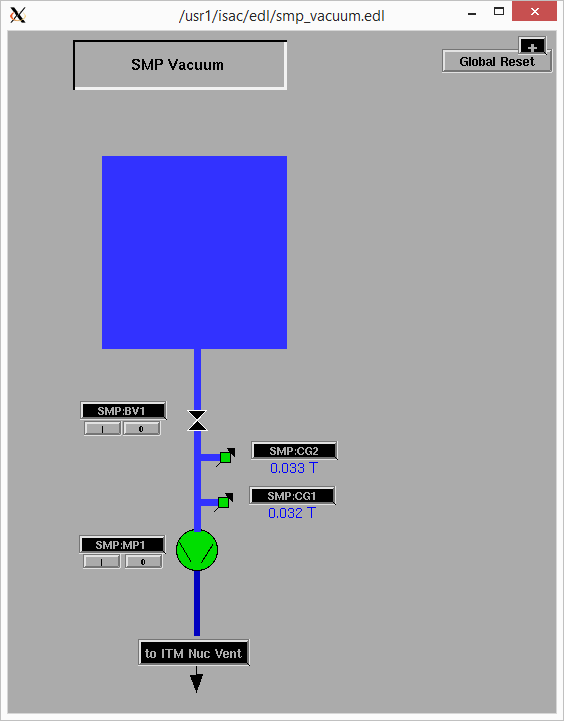
Friday, July 26, 2019, 15:43, Isaac Earle, Safe Module Parking, Development, , , SMP vacuum control system completed
|
The SMP vacuum control system has been wired and setup to be controlled from EPICS. Backing valve control (SMP:BV1) was tested by connecting to the turbo pump solenoid on TM3 located in the silo directly north of the SMP. The SMP pump (SMP:MP1) was turned on and off through the EPICS interface and responded as expected. Both convectron gauges (SMP:CG1 and SMP:CG2) responded as expected when the pump was turned on. The readings from the two gauges were consistent throughout the mili-Torr range.
The work was done by Ray Mendoza under WP I2019-07-24-4 (work request #5239).
|
|
Friday, October 25, 2019, 06:43, David Wang, Safe Module Parking, Development, TM3, , SMP vacuum
|
TM3 was moved into SMP Oct 25 morning. After two nights pumping down, SMP CG1 read 30mtorr this morning. The pump is stopped. SMP will be vented soon for TM3 moving back to silo. |
|
Monday, October 28, 2019, 12:00, Isaac Earle, Safe Module Parking, Development, , , SMP shielding attenuation measured & compared to theoretical values
|
The attenuation of the SMP shielding was measured as part of SMP commissioning (Document-170404, R1, Section 4, Test #8)
The field on the shutter side of TM3 was measured without any shielding as it was removed from a storage silo. At 0.5m from the edge of the module the maximum field was 5.00mSv. After installation into the SMP the maximum field outside the SMP shielding at 0.5m from the edge of the module was found to be 27uSv/hr. The resulting attenuation is 185x
Expected attenuation was calculated by Joe Mildenberger assuming that the majority of the activated components in that module are either copper or aluminum. With 6" of steel shielding (SMP shield vessel plus vacuum vessel), the attenuation factors were found for the following isotopes:
Na-22 (created in Al): 115
Co-60 (created in steel (Fe) or Cu): 70
Mn-54: (created in steel (Fe) or Cu): 200
Based on these figures, the measured result of 185 seems to be reasonable. |
|
Tuesday, October 22, 2019, 16:26, Isaac Earle, Safe Module Parking, Development, , , SMP shield box grounding
|
A braided grounding strap was attached to the aluminum gear box support on the SMP shield box structure, and grounded by attaching it to the exterior of an electrical conduit located in the south-west corner of the B2 area at the top of the silo in that corner. The braiding was also connected to the stainless steel support structure for the SMP vacuum pump. |
|
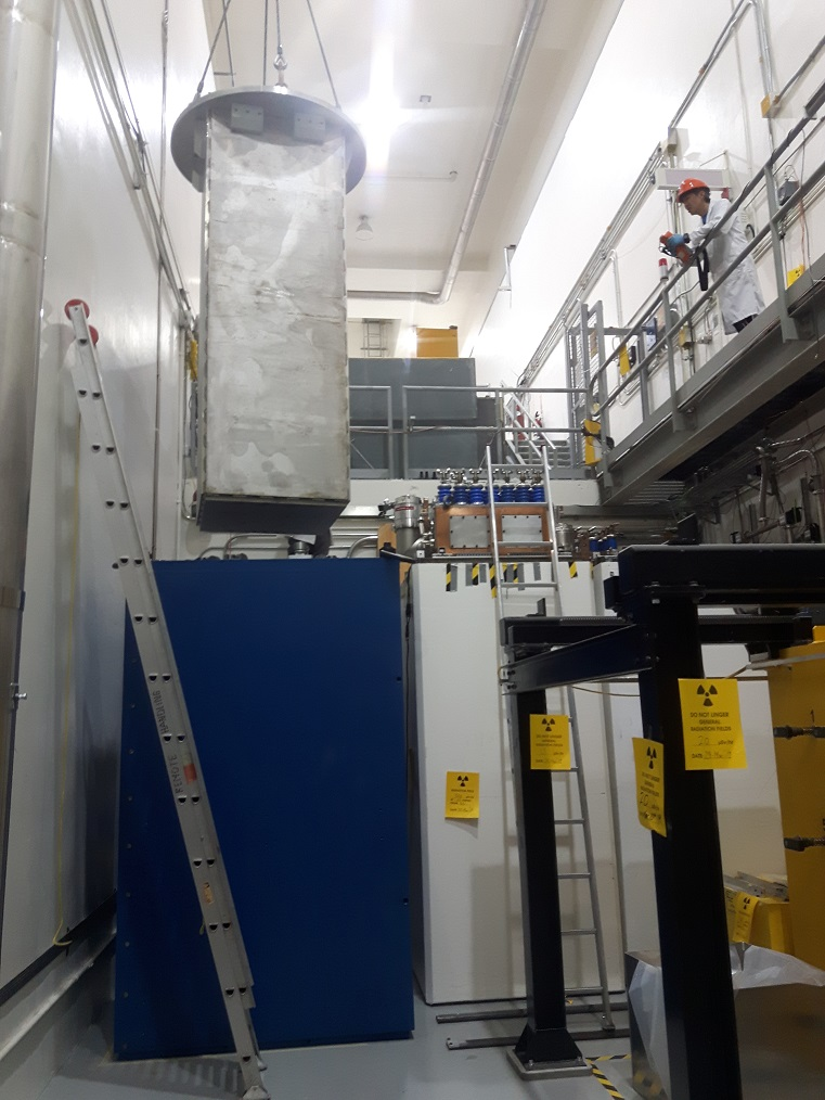
Monday, February 11, 2019, 10:26, Isaac Earle, Safe Module Parking, Development, , , SMP shield box and vacuum vessel moved to Target Hall 6x
|
On February 8th the SMP shield box (IRH1675) and the vacuum vessel (IRH1806) were both raised from a horizontal to vertical orientation in the ISAC-1 Experimental Hall. Hamilton "Mini-Mite" S-MM2-43FS caster wheels were then installed on the base of the shield box and it was lowered down the hatch to the B2 level. The vacuum vessel was then lowered into the shield box, supported by the rollers, as designed. The shield box and vessel combination were then moved south along the steel plated floor until positioned under the hatch leading to the Target Hall. Movement along the floor was achieved by pushing the back of the vessel with an electric fork truck and pulling from the front with a cable winch attached to a plate mounted in the floor in the SHC service area, centered east/west between the Ante Room doors. The fork truck alone was sufficient to move the assembly on the smooth section of the plates, but the winch was needed on the section paitned with textured grit. The vacuum vessel was then lifted into the Target Hall and placed in a temporary storage location in the silo area. The shield box was then lifted, casters removed, and then lifted up into the Target Hall. It was a very tight fit with the tubing which has been installed on the SHC and NHC ducting for the new flow meters, but the move was completed without causing damage. The shield box was placed on the B2 level in the Target Hall where some final tapped holes will be added on the exterior before moving to the final installation location.
|
|
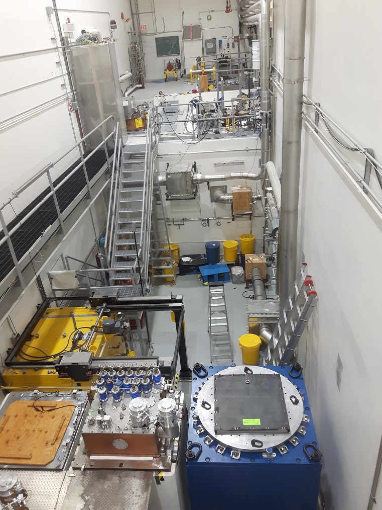
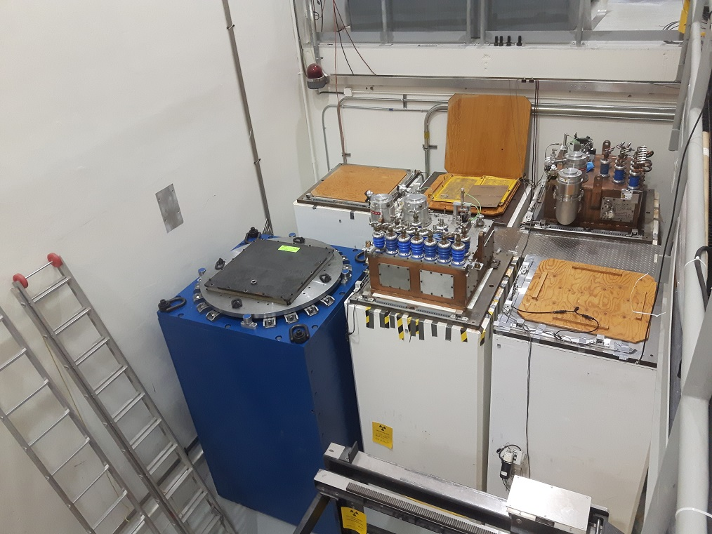
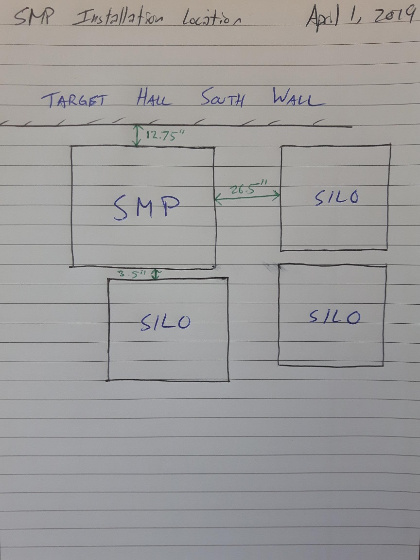
Monday, April 01, 2019, 14:56, Isaac Earle, Safe Module Parking, Development, , , SMP shield box and vacuum vessel installed in final location
|
Last week drilling of the additional required holes in the SMP shield box was completed in the Target Hall. This morning the shield box (IRH1675) was moved to its final installation position in the silo area on the B2 level. The vacuum vessel (IRH1806) was then installed inside the shield box. The center of the vacuum vessel is 2-3" north of the south travel limit of the crane. Photos as well as measurements of the final position are attached below.
|
|
Thursday, June 20, 2019, 15:09, Isaac Earle, Safe Module Parking, Development, , , SMP motor wiring inspected by electrician
|
The AC wiring for the SMP motor was inspected by Randy Boehm (TRIUMF electrician) as recommended by Franco Mammarella (TRIUMF electrical engineer). After inspecting the system Randy required the following changes:
- AC wiring inside the control panel be increased to 16awg minimum (14awg preferred)
- Wiring between the control panel and motor control box be increased to 14awg
- Power cable to the motor be increased to 14awg
- Current rating for MS connectors be checked and replaced if below 10A
- Prefer that motor control box components be relocated to the control panel to reduce number of AC wires and connections (preferred but not mandatory)
- A dedicated ground wire is required in the cable going to the motor (if not already in place)
After these changes have been made the inspection will be repeated.
July 31, 2019 update:
Items 1, 2, 3, and 6 from above were completed. 14awg wiring was used for wiring inside the control panel (Item 1). Current rating for the MS connectors was checked and is over 10A (Item 4). Motor control box components were not relocated to the control panel at this time (Item 5).
Randy repeated his inspection today, and approved of the updated 120V wiring.
Adam updated the SMP electrical and control schematics (IRH1868-1874) |
|
Friday, January 11, 2019, 13:59, Isaac Earle, Safe Module Parking, Development, , , SMP motor selection decision
|
SMP drivetrain design work is currently underway. Alejandro has selected a suitable 1200:1 reducer which will give a vessel rotation speed of 0.21rpm with a 1725rpm motor (deemed sufficiently close to the SHC rotation speed of 0.17rpm). The reducer however is only rated for 0.33hp, and Allon's analysis recommended we use a motor of at least 0.4hp
From his calculations the expected power required to turn the loaded vessel is 0.2hp (see Document-161943, p3). The higher figure of 0.4hp in his final recommendations comes from the power rating of a 40 tooth sprocket (the driver sprocket) with a No. 50 roller chain operating at 10rpm (the lowest speed shown on the table) - meaning this driver sprocket arrangement can handle up to 0.4hp. We discussed this on the phone on January 4th and agreed that a 1/3hp motor could be used which will match the reducer Alejandro selected, and will supply sufficient power given that calculations indicate only 0.2hp is required.
Once the vessel is installed in the shield box a test will be performed to determine the actual torque (and power) required to turn the vessel. If the value differs significantly from the calculated value the design will be revisited. |
|