| |
ID |
Date |
Author |
Category |
Type |
Module |
Target/Number |
Subject |
|
|
2653
|
Friday, August 09, 2024, 19:01 |
David Wang | ITW | Standard Operation | TM3 | TiC#8. | TM3 has been connected in ITW. |
TM3 has been connected in ITW. See attachment for checklist. |
| Attachment 1: TM3_TiC#8_connection_in_ITW_checklist.pdf
|


|
|
|
759
|
Friday, October 10, 2014, 10:47 |
David Wang | Conditioning Station | Development | TM3 | | TM3 has been connected in CS |
TM3 has been connected in CS. All water supplies are bypassed theTM3 on the top of the service cap. TM3 TP2 was difficult to start. It is started finally after couple of time try.The pump runs fine now. |
|
|
2652
|
Friday, August 09, 2024, 18:20 |
David Wang | ITW | Standard Operation | TM3 | TiC#8 | TM3 has been moved from SHC to ITW. |
With TiC # 8 installed, TM3 has been moved from SHc to ITW. The move is smooth. |
|
|
2750
|
Thursday, January 16, 2025, 14:21 |
David Wang | Conditioning Station | Standard Operation | TM3 | No target | TM3 electrical check at TCS under good vacuum |
A complete TM3 electrical check at TCS under good vacuum has been done. Pin 14 to 60KV only has 8K ohm on ohmmeter check , and it's about 2Kohm @250V Megga. It's low in resistivity. The pin 14 is for thermocouples only so no big concern. The rest things are good. See attachments. |
| Attachment 1: TM3_electrical_check_@TCS_page_1.pdf
|

|
| Attachment 2: TM3_electrical_check_@TCS_page_2.pdf
|

|
|
|
537
|
Tuesday, November 12, 2013, 09:51 |
David Wang | ITE | Standard Operation | TM3 | | TM3 disconnection |
TM3 has been disconnected this morning and purged all HV water lines. I found the power plug for all turbo pump fans wasnt connected during the last run. That maybe the one of the reason on that ITE TP3 failure. |
|
|
1526
|
Saturday, May 06, 2017, 13:30 |
Aurelia Laxdal | Conditioning Station | Repair | TM3 | no target | TM3 current limiting |
Today the voltage was raised from 65kV to 65.7kV. After about 10min at this level TM3 started current limiting. TM3 was not sparking when this happened.
ISAC OPS turned it OFF and then tried to ramp it back ON, but could not do it due to the current limiting.
I turned OFF/ON the PS (locally) 20ming ago and and then tried to get it back from the Control Room, but around 4-5kV it started current limiting.
Turned everything OFF on EPICS for the time being. We'll investigate on Monday.
Over the night the sparking rate at 65kV was from 6 to 2 sparks per hour. It tripped OFF once over the night: backing valves closed, tripping the turbos, tripping IG1 and turning OFF the BIAS. At that time ISAC OPS got it back smoothly. |
|
|
1507
|
Wednesday, April 26, 2017, 13:35 |
chad fisher | South Hot-Cell | Repair | TM3 | | TM3 containment box removed |
the containment box has been removed from TM3. |
|
|
2630
|
Thursday, July 04, 2024, 01:20 |
Carla Babcock | ITE | Development | TM3 | SiC#46 | TM3 conditioning with protons |
Initial Summary:
TM3 sparking behaviour in ITE has been very disruptive both with and without protons. Protons are at 60uA, target heater at 540A. Max voltage achieved so far is 51kV, limited by time and a current limit on the BIAS supply.
The ITE:EL trips off every couple of minutes. Just needs to be restarted. Mike investigated and found that the trip is happening inside the power supply, then a moment later the canbus is defining the supply off when it cant get it to respond. Trip frequency decreased over time but still disruptive.
All the waterflow signals, including ones controlled in the cyclotron system, were tripping off regularly. These have all been forced, then we implemented a 5s delay in the ISAC waterflow interlocks. This seems to have solved the issue.
The ITE:BIAS supply has also been limited at 500uA instead of 5mA. Probably something hardcoded into the canbus - this was fixed by Keiko and the hardcode limit was set to 20%(?) of 5mA.
TM3 has been very sparky, even at low voltages. I can't understand why. A new ground path would be explicable but the excessive sparking is difficult to understand.
Possible avenues:
- make sure the module outer surface is connected through a copper sheet to the sheet on the wall.
- check that special ground still grounds all the gnd power supplies in the electrical room - this I checked but some of the grounds are connected through wires instead of sheets, this can be improved.
- try running the module with only HV hooked up and nothing else.
- try running TM3 in ITW.
- Search work permits and shutdown jobs for any changes made to the system that could affect this.
- hope there is a software solution for the EL problem, or start moving towards PLC control - no software solution because the canbus card is only reacting to the power supply refusing to turn on, so it seems the issue originates in the PSU. Moving to PLC is possible but may not help and increases the risk of frying the PLC module.
- Add a spark gap or limiting resistor to the EL somewhere. Resistor only helpful if the EL itself is sparking. Difficult to find a spot for the spark gap.
- Get a bipolar supply that can sink the current of a spark and replace the EL supply. - Tomislav doesn't seem to think this is viable.
- Add protection on the controls cables.
Spark recording:
60uA/50kV/540A July 3 02:30 - 05:30 : average of 50 sparks per hour. data file https://isacwserv.triumf.ca/onlylocal/isacdata/ITE_TM3_SiC46_HVConditioning_2_20240704
60uA/32kV/540A July 3 19:15 - July 3 21:45 : average of 8.4 sparks per hour. data file https://isacwserv.triumf.ca/onlylocal/isacdata/ITE_TM3_SiC46_HPSIS_HVConditioning_20240704
50uA/42.8kV/540A July 4 8pm - July 5 2pm : average of 20 sparks per hour, or if you cut out the last two hour that were very sparky, 14 sparks per hour. data file http://isacwserv.triumf.ca/onlylocal/isacdata/TM3commissioning_July4_52024.dat
50uA/42.8kV/540A July 8 00:00 - July 8 18:00 : average of 3.4 sparks per hour. data file http://isacwserv.triumf.ca/onlylocal/isacdata/TM3commissioning_July82024.dat
50uA/42.8kV/540A July 10 10am - 3pm : 3.6 sparks per hour
50uA/53kV/540A July 17 5am - 10am : 4 sparks per hour
45uA/53kV/540A July 20 8pm - July 21 6:30am : 24 sparks in 11 hrs, avg 2.2 sparks per hour.
EL trip recording (first 2 entries from the archiver, verify with ops elog):
50uA.42.8kV/540A July 4 23:00 - July 5 16:00 : 9 trips, average 0.5 trips per hour
50uA/42.8kV/540A July 6 12:00 - July 7 03:00 : 6 trips with 2.5hrs off, average 0.5 trips per hour
50uA/42.8kV/540A July 7 05:00 - July 8 18:00 : no trips in past 30hrs. Last trip July 7 at 3am.
50uA/42.8kV/540A July 10 3pm - still no EL trips
50uA/53kV/540A July 16 8pm - July 17 10am : 3 trips in 6 hrs. Note cable in EL circuit got burned so EL is running at only ~4kV
45uA/53kV/540A July 17 3pm - July 18 9:30am : 7 trips in 18hrs
45uA/53kV/540A July20 14:00 - July 21 6:30 : 5 trips in ~17hrs
2024-11-15 EDIT, Alexander Shkuratoff:
I was not involved in this run, but I have gone through all the Elogs for TM3 up to this point and summarized all the data dumps at the bottom, so I may as well do it here.
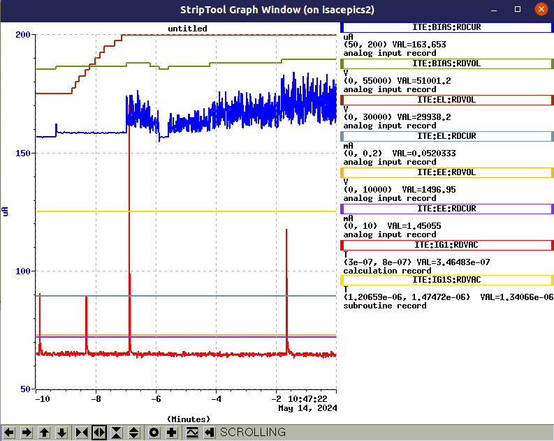
Additionally, there is no Elog entry for August 18, 2024 for which TM3 commissioning continued in ITW, but I have found the following StripTool data:
|
|
|
2591
|
Tuesday, May 14, 2024, 15:27 |
Carla Babcock | ITE | Development | TM3 | UCx#44 | TM3 conditioning and testing in ITE |
Tuesday, May 14, 2024, 10:26 :
Ramping up bias/EE/EL on ITE - will see if the HV cage in the pit can hold 60kV or not.
At around 50kV the bias read current starts to get jumpy. Doesn't look like its an issue for the voltage, but definitely instability increases.
Occasional sparks seem to increase the EL current significantly...
David heard some sparks in the target hall. Looks like from heat shield feed through to the top of the cage. Several sparks heard in the TH also changed the einzel lens draw current significantly. These feethroughs are not far from each other so could be related.
Apparently the sparking also tripped off all the optics and heaters in ITW, by changing the state of the water flow interlock. Interesting and not seen ever before. Will test again with the cage off, rather than risk tripping ITW again.
Tried ramping up the voltage on just the EE. Seems the limit is 7kV - at that level it gets sparky and unstable. Should be investigated (should hold 10kV) but not critical for module function.
Wednesday, May 15, 2024, 10:05 :
HV cover was removed this morning and the MAA was locked out.
Started ramping things up, was very easy until around 58kV. At 59.5kV a spark tripped off the EL. Canbus controller had to be power cycled to fix it. Bias current is much more stable in this configuration.
Ramped up again while listening from the TH to see if it was sparking outside. Went slowly to 60kV (left EL at 29kV) and didn't see any outside sparks in the first 10 mins, couple sparks in vacuum. But after 15 mins a spark seems to have fried the EL canbus card. We were not in the TH so not sure if it was on the outside or not.
After 2 hours a spark tripped off both ITE and ITW. Looks like it makes a water interlock go bad momentarily, but after the trip the interlocks seem fine.
Tuesday, May 28, 2024, 16:41
Running TM3 at any voltage in ITE produces fairly destructive sparks. There are not many but so far they have tripped off all optics in ITW, the water flow interlocks (later forced on to prevent this), the EL (generally comes back but killed the canbus card once), destroyed two vacuum gauge controllers, and may have contributed to the cathode short on ITE-TM3-UC44-LP-FEBIAD.
The conditioning process seems to go as planned, but the occassional inevitable spark still trips things, which is making it difficult to run stable.
Will continue with regular HV conditioning to see if this helps. Control over the current limit on the ITE:BIAS supply would also help, but seems a complicated thing to add according to Roberto.
TM3 sat fine at 53kV overnight and at 58kV for several hours. The EZL trips off maybe once every 2-3hrs or so, which is not ideal but liveable. This was with the TGHT and CHT power supplies forced, so not sure if we would know if they would have tripped...
CONCLUSIONS:
- TM3 has been commissioned for beam delivery after one week of delivery of UF to TITAN using a FEBIAD ion source in anode bias mode. Cathode mode was also used, so all functionality of the target except IGLIS current/voltage delivery through the mutlipin has been tested successfully.
- TM3 still requires commissioning at high voltage with protons to be considered fully commissioned, this will be done July 2 2024 due to problems with the cyclotron.
|
|
|
1347
|
Thursday, September 08, 2016, 16:28 |
David Wang | Conditioning Station | Repair | TM3 | | TM3 blue insulators have been replaced. |
All TM3 blue insulators except Gas,EL, and 60 KV common on top of the module have been replaced with new designed insulators. The new blue insulator for gas line need to be modified to fit for the bent on the gas line. EL, and 60KV common blue insulators were replaced during last time TM3 refurbishment so they are relative new, and not replaced this time. All seals related to the blue insulators are changed to new seals. The o- r-ing surfaces for o-ring 221 inside the new insulators are rougher than old parts. The module top need to be leak checked. |
|
|
616
|
Friday, March 07, 2014, 12:45 |
David Wang | ITE | Standard Operation | TM3 | | TM3 and ITE air to vacuum leak check and TM3 water lines helium test. |
With TM3 located in ITE, All air to vacuum seals on ITE primary and secondary vacuum vessel have been leak checked with leak detector hooked directly on the TM3 service cap.The base LR :00xE-9atm.cc/sec. The ITE IG1 was 1.6xE-6 torr which was good. No leak has been found during the checking.Also, the TM3 water lines(except HS) had been pressurized with 70 psi helium on each for 2 minutes. There was no response during the test. The ITE and TM3 are good on leak checking.See attachment pictures |
| Attachment 1: 001.JPG
|

|
| Attachment 2: 002.JPG
|

|
| Attachment 3: 003.JPG
|

|
| Attachment 4: 010.JPG
|

|
| Attachment 5: 013.JPG
|

|
|
|
2611
|
Friday, June 14, 2024, 11:55 |
David Wang | South Hot-Cell | Standard Operation | TM3 | UCx#44 | TM3 UCx#44 after operation electrical check at SHC |
TM3 UCx#44 after operation electrical check at SHC . see attachment.
Carla: Looks like the short on the cathode observed while trying to operate the FEBIAD in cathode-bias mode is still there. Will do investigations in the hot cell during disassembly. |
| Attachment 1: TM3_UCX#44_after_operation_electrical_check.pdf
|

|
|
|
769
|
Monday, October 20, 2014, 09:13 |
David Wang | Conditioning Station | Development | TM3 | | TM3 TP2 failed |
TM3 TP2 stopped working this morning at 4:00 AM. I tried to start it but failed. On normal start mode , It could not pass 6K RPM. On soft start mode , the pump cant pass 17KRPM. Talked with Anders, We are not going to replace this pump since we are not going to run this module for a while. I will stopped all vacumm pumps on CS and TM3 this morning. |
|
|
321
|
Wednesday, April 24, 2013, 11:48 |
chad fisher | South Hot-Cell | Repair | TM3 | | TM3 Source Tray Removal |
Work on TM3 source tray removal started at 10:40 am today.
The containment box has been removed, and disconnection of the optics tray is 90 complete.
Pictures can be found in the April Refurb Work Folder in the tm3 rev3 refurb pictures folder. |
|
|
326
|
Tuesday, April 30, 2013, 07:47 |
chad fisher | South Hot-Cell | Repair | TM3 | | TM3 Source Tray Removal |
The source tray has sucessfully been removed from TM3.
I will put a report in the TM3 rev 3 docushare directory as there were some items of note during this procedure. |
| Attachment 1: IMG_1043[1].JPG
|
![IMG_1043[1].JPG](../RH-ISAC/130430_074745/IMG_1043[1].JPG.png "IMG_1043[1].JPG")
|
|
|
2648
|
Thursday, August 08, 2024, 13:58 |
David Wang | South Hot-Cell | Standard Operation | TM3 | SiC #46 | TM3 SiC#46 electrical check at SHC with target on (After operation) |
ABCD is short to 60KV bias. Othjer are ok. see attachment.
Found afterwards that this short was due to sparking through the multipin wire insulation where the wires pass behind the TBHT block "C". See fault 17265. |
| Attachment 1: TM3_Sic_46_after_run_E_check.pdf
|

|
|
|
1510
|
Wednesday, April 26, 2017, 17:55 |
Aurelia Laxdal | South Hot-Cell | Repair | TM3 | no target | TM3 Schedule updates at the South Hot Cell and CS |
Please see TM3's Updated Schedule (the current schedule) at the SHC and TCS.
For the record I am uploading TM3's Initial Schedule at the SHC and TCS. |
| Attachment 1: April_�_May_2107_TM3_Updated_Schedule_at_the_SHC_and_TCS.docx
|
| Attachment 2: April_�_May_2107_TM3_Initial_Schedule_at_the_SHC_and_TCS.docx
|
|
|
391
|
Tuesday, July 02, 2013, 09:37 |
chad fisher | South Hot-Cell | Development | TM3 | | TM3 Rev.2 Source Tray Disposal |
Tm3 Rev.2 source tary has been transfered to the vault tunnel storage. |
|
|
424
|
Thursday, August 22, 2013, 19:38 |
Grant Minor | South Hot-Cell | Repair | TM3 | | TM3 Rev 3 source tray - water blocks connected and torqued |
After a great struggle with the water block jigs, the TM3 source tray was finally advanced fully into the service tray and all water blocks were connected and torqued to spec in the hot cell by Chad Fisher.
Notes and description of problems encountered during the installation:
- The water lines for the optics tray interfered with the module-side water block jig, and had to be bent out of the way to clear while advancing the tray (see attached photos)
- The water block jig on the source tray side was too low relative to the module side, and had to be eventually unbolted completely from it's mounting bracket in order to raise it up into alignment
- A piece of aluminum plate was placed under the jig, and the pneumatic table was raised in order to move the jig upwards
- After many repeated attempts to engage the blocks by pressing the jigs together, it was discovered that some of the blocks had rotational misalignment with their respective counterparts on the module side, preventing the pins from engaging properly
- By looking through the bolt holes on several of the blocks, it was possible to determine which direction they had to be rotated
- Chads polishing tool was used to apply some torque to rotate the source-tray-side water blocks slightly so proper alignment of the pins could be achieved
- See the attached photo which indicates which blocks had to be rotated (blocks 5, 6, 9, 10, and 11)
- The blocks had the bolts installed and were also torqued in the numbered order shown in the attached photo
Next steps are to remove the water block jigs, re-connect the loosened brackets for the remaining water lines (entrance window, optics tray), re-install the containment box and associated VCR connectors, video inspect, and leak check. |
| Attachment 1: IMG_0838.JPG
|

|
| Attachment 2: IMG_0841.JPG
|

|
| Attachment 3: IMG_0846.JPG
|

|
| Attachment 4: IMG_0848.JPG
|

|
| Attachment 5: TM3_water_blocks_rotated_for_fit_22Aug2013.jpg
|

|
| Attachment 6: IMG_0877.JPG
|

|
|
|
431
|
Tuesday, August 27, 2013, 17:18 |
Grant Minor | Conditioning Station | Repair | TM3 | no target | TM3 Rev 3 source tray - prelminary leak check results at CS |
David Wang started a helium leak check on TM3 at the CS this morning.
David will create an e-log once his check is complete, but here are the preliminary results:
- target oven +/- OK
- mounting support plate OK
- ionizer tube heater +/- OK
- extraction electrode OK
A large leak was found in the heat shield circuit:
- The module pumped down with the leak rate stabilizing at 4.8xE-9 atm.cc/sec
- 60 psi helium was applied to the heat shield fitting on the right side of the Y-shaped connector (see attached sketch, each side of the "Y" is separated by a face to face metal contact only, i.e. no o-ring seal separates supply and return water)
- The maximum leak response was detected in 10 seconds, with base pressure rising from 2.0E-2 torr to 2.8xE-2 torr
- The helium was vented from the line by using an allen wrench to open the valve on the water quick-connect (see attached photo)
- The module continued pumping down, and after some time, the allen wrench was used again to open the valve, but air rushed inside, indicating vacuum was being drawn inside the water line through the leaking interface
- As the module continued to pump, this vacuum vent air rush inside the water line could not be reproduced by opening the valve again with the allen key
The module is currently pumping down at the Conditioning Station. We will leak check the remaining lines tomorrow with whatever base leak-rate we have achieved, and then move TM3 to the Hot Cell for further diagnosis. |
| Attachment 1: TM3_leak_check_at_CS_27Aug2013.JPG
|

|
| Attachment 2: sketch_TM3_water_feedthru_27Aug2013-1.pdf
|

|