| ID |
Date |
Author |
Category |
Type |
Module |
Target/Number |
Subject |
|
1921
|
Wednesday, May 15, 2019, 16:06 |
Isaac Earle | Safe Module Parking | Development | | | SMP module support flange installed and leak checked |
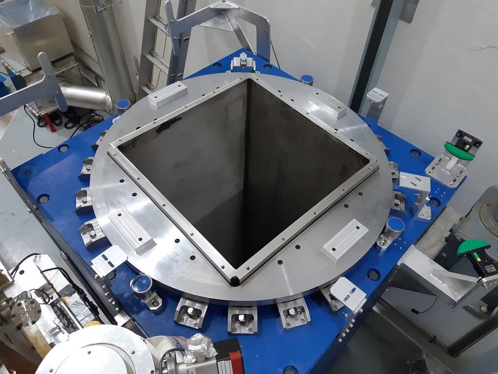
The SMP module support flange sub-assembly (IRH1755) was installed today according to drawing IRH1683. Dow Corning 111 sealing compound was used to keep the o-ring adhered to the lower groove during transportation and installation. The TCS shield plug (IRH1646) was then installed on the SMP module flange which has vacuum connections for leak checking. Vacuum was pulled on the SMP vessel using the Varian 979 leak detector. After approximately 3.5 hours of pumping the test port pressure was at 2.4E-2 Torr and leak rate was 7.9E-8atm*cc/s. Helium was configured with the regulator set at 10psi and flow rate of >10 bubbles per second in Windex and then applied slowly around the perimeter of the vacuum flange (IRH1686) and it's mating components on both the top and the bottom. There was no response on the leak detector indicating the seals on both sides of the module flange are leak tight.
|
|
1925
|
Friday, May 17, 2019, 16:46 |
Adam Newsome | Safe Module Parking | Development | | | SMP Controls Installation Update |
The following controls-related items were installed for the SMP project:
- Cable tray
- Main control panel
- Motor starter box
- Wiring from limit switches and rotation motor to main control panel
- Air fittings at supply (quick disconnect)
- Main air supply hose from supply to control panel (quick disconnect)
- Air tubing from lid control valve at control panel to lid cylinders
Air fittings stem off existing air supply lines on the South wall, below a manual shutoff valve. A quick disconnect was installed. When SMP is not in use, manual shutoff valve should be left off.
Main control panel and motor starter box were mounted on the North wall. Wire duct runs from the main control panel to the grated floor. Cabling/air runs underneath the mezzanine platform, along existing and new cable tray, to the SMP.
Cable tray was installed on the South wall, from the corner to the SMP module. A cutout was made to accommodate for existing tubing. An additional ~1 ft. of tray will be added to the end, near the corner, at a future time.
Remainder of installation work to be done before commissioning:
- Mount and install new Opto-22 module
- Chain new Opto-22 module to existing one (power, comms) below mezzanine on North wall |
| Attachment 1: IMG_20190417_100838.jpg
|

|
| Attachment 2: IMG_20190417_100843.jpg
|

|
| Attachment 3: IMG_20190517_162230.jpg
|

|
| Attachment 4: IMG_20190517_162305.jpg
|

|
|
1930
|
Thursday, May 23, 2019, 11:22 |
Travis Cave | South Hot-Cell | Maintenance | | | Removing garbage from the south hot cell. |
A 55 Gal. drum was remotely lowered into the south hot cell. It was then filled with compressable waste. Then the drum was remotely removed from the south hot cell. The drum measured about 20microSv/hr upon removal from the south hot cell. |
|
1937
|
Monday, June 10, 2019, 14:13 |
Travis Cave | Spent Target Vault | Standard Operation | | | Old TM#4 source tray moved |
The old TM#4 source tray in the south hot cell was moved to the spent target vault. The tray had a low of 7.5mSv/hr to a high of 22.1mSv/hr though a 390 degree rotation. |
|
1944
|
Thursday, June 20, 2019, 15:09 |
Isaac Earle | Safe Module Parking | Development | | | SMP motor wiring inspected by electrician |
The AC wiring for the SMP motor was inspected by Randy Boehm (TRIUMF electrician) as recommended by Franco Mammarella (TRIUMF electrical engineer). After inspecting the system Randy required the following changes:
- AC wiring inside the control panel be increased to 16awg minimum (14awg preferred)
- Wiring between the control panel and motor control box be increased to 14awg
- Power cable to the motor be increased to 14awg
- Current rating for MS connectors be checked and replaced if below 10A
- Prefer that motor control box components be relocated to the control panel to reduce number of AC wires and connections (preferred but not mandatory)
- A dedicated ground wire is required in the cable going to the motor (if not already in place)
After these changes have been made the inspection will be repeated.
July 31, 2019 update:
Items 1, 2, 3, and 6 from above were completed. 14awg wiring was used for wiring inside the control panel (Item 1). Current rating for the MS connectors was checked and is over 10A (Item 4). Motor control box components were not relocated to the control panel at this time (Item 5).
Randy repeated his inspection today, and approved of the updated 120V wiring.
Adam updated the SMP electrical and control schematics (IRH1868-1874) |
|
1946
|
Thursday, July 04, 2019, 08:57 |
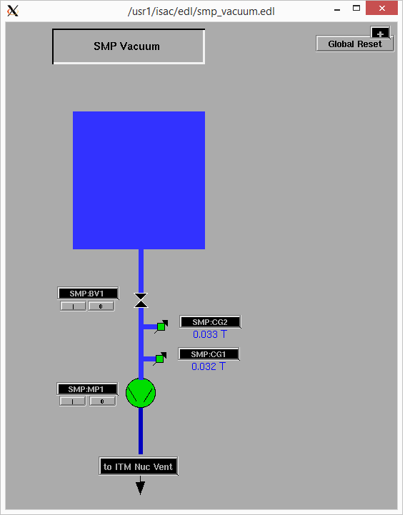
Isaac Earle | Safe Module Parking | Development | | | SMP vacuum system installed |
July 3:
- Assembled exhaust line flexible hose and fittings as per ISK0529 Rev D then leak checked: 1.4E-1 Torr test port pressure, 1.1E-7 atm-cc/s leak rate, no response to helium spray at both ends of flexible line (all vacuum fittings purchased from Kurt Lesker under Requisition #1046936)
- Connected exhaust of SMP vacuum pump to nuclear ventilation duct using flexible hose assembly as per ISK0529 Rev D
- Installed convectron gauges at pump inlet as per ISK0529 Rev D
- Installed TCS plug block (IRH1646) in SMP
- Connected plug block vacuum port to SMP pump using flexible corrugated hose
- Connected SMP:CG1 to portable pressure display: ~700Torr
- Turned on SMP:MP1 at 4:17pm, after approximately 25 minutes was down to 75 Torr, at 1hr 40 minutes was 90mTorr, left pumping over night
July 4:
- Pressure at 4mTorr at 8am, will leave pumping longer to see if it gets any lower
- Submitted Work Request #5239 to PLC Controls for wiring of the pump and convectron gauges and integrations with EPICS
|
|
1955
|
Friday, July 26, 2019, 15:43 |
Isaac Earle | Safe Module Parking | Development | | | SMP vacuum control system completed |
The SMP vacuum control system has been wired and setup to be controlled from EPICS. Backing valve control (SMP:BV1) was tested by connecting to the turbo pump solenoid on TM3 located in the silo directly north of the SMP. The SMP pump (SMP:MP1) was turned on and off through the EPICS interface and responded as expected. Both convectron gauges (SMP:CG1 and SMP:CG2) responded as expected when the pump was turned on. The readings from the two gauges were consistent throughout the mili-Torr range.
The work was done by Ray Mendoza under WP I2019-07-24-4 (work request #5239).
|
|
1970
|
Friday, August 23, 2019, 14:27 |
Isaac Earle | Safe Module Parking | Development | | | SMP camera video cabling installed and tested |
Installation of the video lines for the SMP cameras was completed yesterday according to IRH1670 Rev B. All four cameras were confirmed to be displaying properly in the crane control room. The cameras are powered from an outlet wired to circuit 35/37 on Panel #443 (located in the NHCSA). This is independent from the power supply for other existing camera systems in the Target Hall. The SMP turntable was rotated through the full range of motion (reached CW and CCW limits) and the cable routing and reel take-up system performed as expected. |
|
1971
|
Tuesday, August 27, 2019, 13:12 |
Adam Newsome | Safe Module Parking | Development | | | SMP Remote Control Wiring Inspection |
The wiring for the SMP remote control module was inspected by Joel Semilla (TRIUMF electrician). The module was plugged in to verify there were no issues. No changes were suggested, and then wiring was approved. |
|
1983
|
Tuesday, September 10, 2019, 14:04 |
David Wang | ITW | Standard Operation | | | ITW water interlock check. |
ITW water interlock check is finished. Everything is good. |
|
1987
|
Wednesday, September 18, 2019, 14:28 |
Travis Cave | Spent Target Vault | Standard Operation | | | Repacking of the targets. |
Three of the five targets in the mini storage have been repackaged into the stronger pail. |
|
1988
|
Thursday, September 19, 2019, 10:11 |
Travis Cave | Spent Target Vault | Standard Operation | | | Repacking of the targets. |
Another target in the mini storage has been repackaged into the new pails. With one remaining to do which will be done on Monday. |
|
1989
|
Monday, September 23, 2019, 13:21 |
Travis Cave | Spent Target Vault | Standard Operation | | | Repacking of the targets. |
All targets in the mini vault have been repackaged and are now ready to be loaded into F-308s. All the target pails have new numbers see attached sheet for details. |
| Attachment 1: Target_Index_2019-09-23_Mini_Vault.pdf
|


|
|
1990
|
Monday, September 30, 2019, 11:27 |
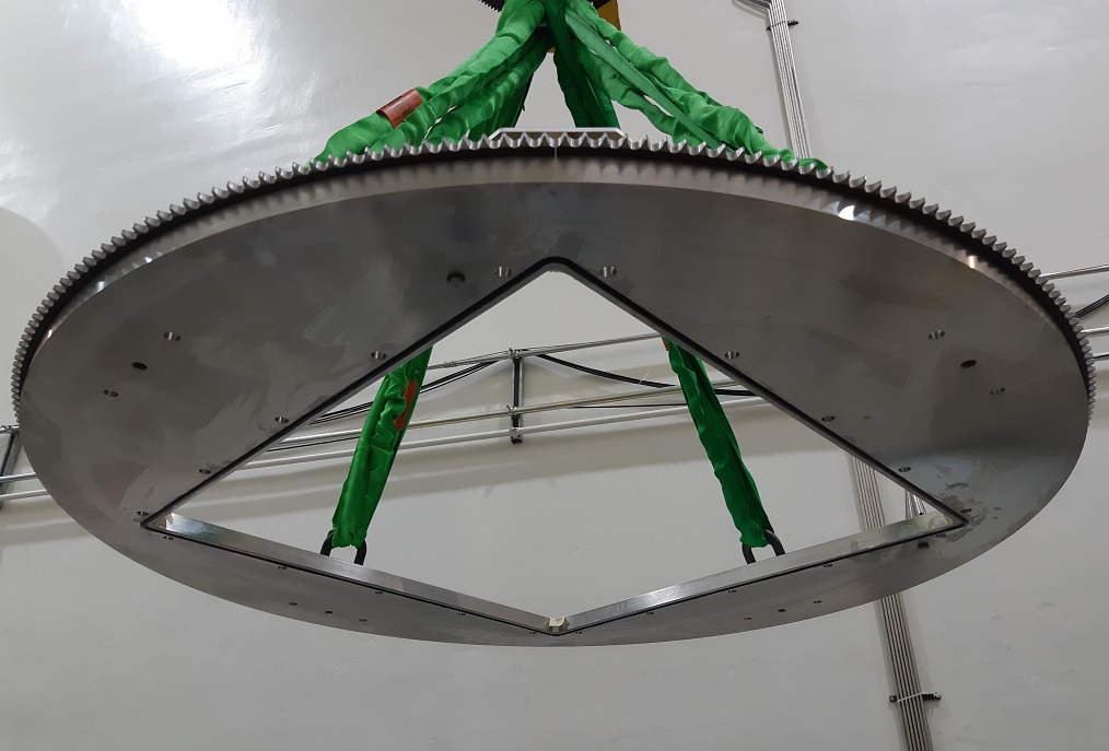
Isaac Earle | Safe Module Parking | Development | | | SMP vacuum vessel modifications completed |
The SMP vacuum vessel welds were reinforced to match the specifications on IRH1710 Rev D. In addition a tube stub was added on the side of the vessel for installation of a PRV. The relief valve installed was Accu-Glass 113150, with 2psi setpoint (not the MDC 420036 model specified on IRH1710 Rev D). The drawing will be updated to reflect this.
Welding was performed in the TRIUMF machine shop. A larger capacity forklift was rented to move the vessel back and forth between the shop and the Meson Hall loading bay where the main crane was used to flip the vessel between welds.
After welding the vessel was leak checked using a blank-off plate (helium leak tight). The vessel was then returned to the Target Hall, the top flange IRH1755 was re-installed, and the TCS shield plug was installed on the flange. The vessel was pumped down over the weekend using the SMP vacuum pump, and reached 8mTorr by Monday morning. A helium leak check was performed in the Target Hall: baseline leak rate 0.0E-9 atm-cc/sec, 0.0E-4Torr port pressure, no response to generous helium spray on PRV and around both seal locations for the top flange.
Remaining re-assembly of the SMP will now proceed. |
|
1997
|
Wednesday, October 02, 2019, 08:25 |
chad fisher | South Hot-Cell | Standard Operation | | ZrC#8 | ZrC#8 PIE |
Heat shield has been removed from ZrC#8. |
| Attachment 1: 20191002_081653[1].jpg
|
![20191002_081653[1].jpg](../RH-ISAC/191002_082344/20191002_081653[1].jpg.png "20191002_081653[1].jpg")
|
|
1998
|
Thursday, October 03, 2019, 10:25 |
Travis Cave | Spent Target Vault | Standard Operation | | ZrC#8 | Spent Target Move |
The spent ZrC#8 was moved from the south hot cell to the spent target vault. It was placed in pail 217 and the pail was placed in slot 3A of the vault, it was 205mSv/hr when removed from the hot cell. Also the pail was filled with junk stuff that included
wire, a wire scanner, IMG guage, target bolts and a water block bolts. Also there are only two spots left in the vault. |
| Attachment 1: Target_Index_2019-10-02.pdf
|


|
|
2005
|
Wednesday, October 09, 2019, 13:28 |
Travis Cave | Spent Target Vault | Standard Operation | | UC#27 | Spent Target Move |
The spent target in the south hot cell has been moved to the spent target vault. It was placed in spot 1B of the vault in pail number 218. See attached for vault details. |
| Attachment 1: Target_Index_2019-10-09.pdf
|


|
|
2006
|
Thursday, October 10, 2019, 16:17 |
Adam Newsome | Safe Module Parking | Development | | | SMP Main Panel: Relay Addition for E-Stop Circut |
An update was made for the E-stop and power supply system in the SMP main panel. Upon testing remote control, it was determined that the Opto 22 AC module was not sufficiently rated to handle the current draw of the motor (5A fuse versus motor 5.7A current draw). The design was modified so that the E-stop chain, which supplies 120 VAC line voltage through the main panel E-stop then the remote module (or local pendant when plugged in), will now activate a relay rather than run directly to the motor and 24 VDC PSU. This means that this E-stop chain will not carry the current draw of the entire system. Rather, the relay that is toggled when the E-stop circuit is closed will supply the system with power - this relay is rated for 15 A so the main 10 A fuse will blow before the relay fails in the event of a current spike. The new relay was installed on Oct 9, 2019. The local pendant was tested at this time and worked as expected (motion control, E-stops). On Oct 10, 2019, remote control was tested again and is working as expected (motion control, E-stops). In the attached schematic screenshot, the modification is CR7. In the image of the panel, this relay is located in the top left.
Edit: TRIUMF electrician Joel Semilla has seen the design change and verified it is acceptable. |
| Attachment 1: Changes_to_IRH1869.JPG
|

|
| Attachment 2: IMG_20191009_153336_-_new_relay_for_E-stop.jpg
|

|
|
2007
|
Tuesday, October 15, 2019, 16:42 |
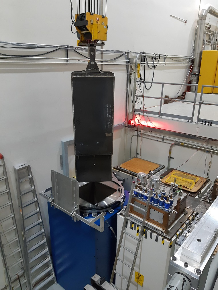
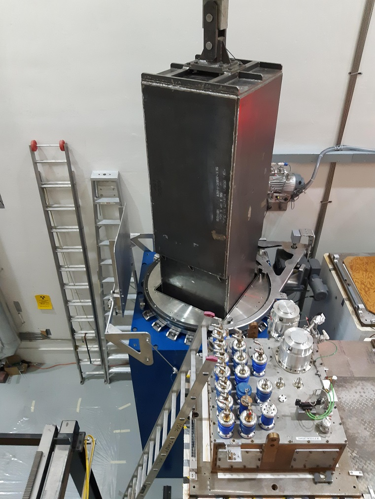
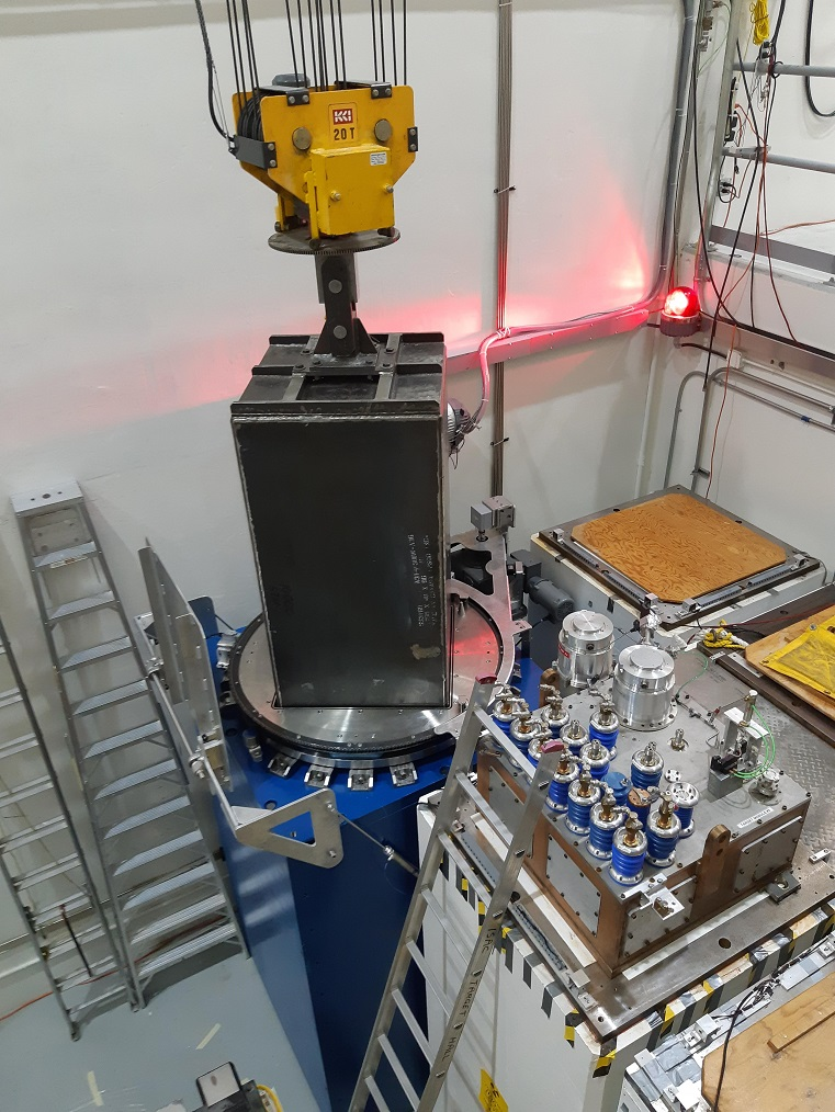
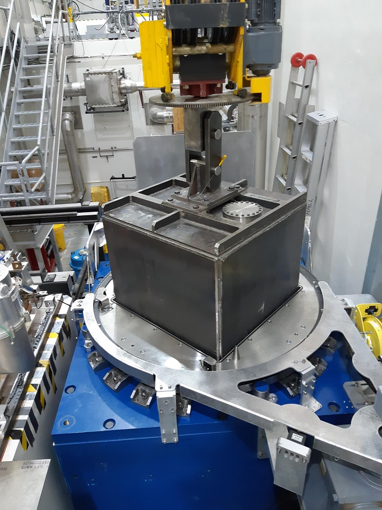
Isaac Earle | Safe Module Parking | Development | | | SMP flange alignment tested using shield plug |
As a preliminary test in preparation for SMP commissioning, one of the steel module shield plugs was installed into the SMP to check the positional and rotational alignment procedures. The following is a summary of the steps performed:
- Shield plug lifted with crane and rotated to an arbitrary (non-orthogonal) position
- Using the crane pendant the shield plug was roughly aligned over the SMP and lowered until the base was within 15cm of the top of the flange
- The SMP flange was rotated to roughly match the orientation of the shield plug
- Precise positioning of module achieved visually from within the Target Hall using crane for NESW position and SMP for rotation
- Module lowered into SMP vessel (not resting on base of vessel)
- Target Hall crane was then set to "Test Mode" and operated from the crane control room
- Crane position with the module centered in the SMP vessel was recorded as E-W: 18.5495m, N-S: 4.9065m
- The shield plug was lifted from the SMP, moved to an arbitrary location in the Target Hall, and set to a different arbitrary rotational position
- The SMP flange was returned to the "centered" position
- The shield plug was moved to the previously recorded location over the SMP and lowered to within 15cm of the top of the flange (using cameras)
- Steps 3-5 were repeated using only camera views to achieve alignment (SMP rotation was controlled using the pendant with instructions by phone from the crane room operator because the module for remote control currently requires a part to be changed)
Official commissioning of the SMP will now be planned as per the commissioning plan Document-170404
|
|
2008
|
Thursday, October 17, 2019, 11:49 |
Travis Cave | Spent Target Vault | Standard Operation | | SiC#31,32 and UC#19,20,21 | Loading F-308 |
The targets in the mini storage have been loaded into the F-308. |