| |
ID |
Date |
Author |
Category |
Type |
Specific |
Subject |
|
|
264
|
Wednesday, June 10, 2020, 08:58 |
Isaac Earle | Development | Other | M9 | T2-M9 and M9-B1 flange scan data |
Laser tracker scan data from 2017 and 2019 attached as a backup. Original files from Beamlines Group who also keep copies on \\trwindata\experimental support\alignment\T2-M9_data |
| Attachment 1: 2017-03-28_meson_hall_t2_with_import_of_2015_data.xit64
|
| Attachment 2: 2019-25-01_meson_hall_t2_data.xit64
|
|
|
265
|
Friday, June 12, 2020, 13:54 |
Isaac Earle | Development | Other | M9 | M9 Q1Q2 water header installed |
The Q1Q2 water header (TB23481) was mounted this morning as per installation drawing TB23400.
Heat shrink tubing was applied to the B1 power cables (two positive, two negative) over the length of cable in the highest field which was showing some signs of radiation damage on the insulation. The tubing used was McMaster-Carr PN 75665K932 (Clear PTFE, 4:1 shrink ratio, 1.0" ID before shrinking), as recommended by Syd Kreitzman. Each piece of tubing is 4' long, and two were used per cable. The first one was shrunk along its full length, then the second piece was only shrunk where it overlaps the first and the remainder was left loose. This was done to minimize time required in the high dose area.
Hand-stacked concrete bricks were removed from the location where the new piping will run to the water header. This is scheduled to take place between July 6-8 |
| Attachment 1: 2.jpg
|

|
| Attachment 2: 1.jpg
|

|
|
|
266
|
Tuesday, July 07, 2020, 13:22 |
Isaac Earle | Development | Other | M9 | M9 Q1Q2 |
The M9 Q1Q2 magnet assembly lift beam has been installed according to drawing TB23401. The side-to-side as well as beam-axis direction adjustment features were tuned so that the assembly is level when lifted.
Aug 5, 2020 update: All fasteners on the lift beam assembly have been torqued according to the specification on drawing TB23401
|
| Attachment 1: 8.jpg
|

|
| Attachment 2: 1.jpg
|

|
| Attachment 3: 4.jpg
|

|
| Attachment 4: 6.jpg
|

|
|
|
267
|
Tuesday, July 07, 2020, 15:13 |
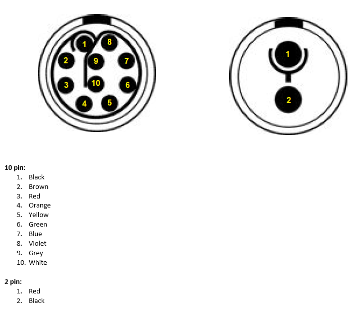
Isaac Earle | Development | Other | M9 | M9 Q1Q2 service stand Lemo connector wiring |
The diagram below shows the wiring for the two connectors on the service stand (the wires running from the stand to the power supplies. (see TB23400 for details)
|
|
|
268
|
Thursday, July 09, 2020, 06:44 |
Isaac Earle | Development | Other | M9 | Alignment of M9 Q1Q2 magnets complete |
Mike Vogel reported that alignment of the Q1Q2 assembly w.r.t. the T2 and B1 flanges was completed on July 7. This was performed in the test stand with the flange positions set to the measurements taken in the 2019 shutdown. Alignment to the theoretical location was achieved within 0.1mm.
The axis of the Q1 and Q2 magnets were aligned to each other previously within similar accuracy. |
|
|
272
|
Wednesday, February 17, 2021, 10:39 |
Isaac Earle | Development | Other | UCN | UCN Target Cask Testing |
A trial run of remote removal of the UCN target was performed using the shielded target cask (TTA0335) developed in 2020. The work took place between Feb 9 - 17 under work permit C2021-02-09-1.
The procedure in work instruction Document-187117 R1 was followed. Draining and purging of the water system as well as venting of helium from the target crypt was performed by Tony Hessels. The remainder of the procedure was carried out by Keith Ng, Maico Dalla Valle, and Isaac Earle. A maximum field of 1.7mSv/hr was measured at 0.5m from the bare target; This is higher than the approximate 500uSv/hr field that was expected, however dose incurred during the work was minimal (Isaac: 0.05mSv, Maico: 0.03mSv, Keith: 0.03mSv).
The cask aligned well to the target arm and no modifications to the cask or UCN hardware were required to carry out the procedure. A few updates will be required to the work instruction document based on discoveries made during the procedure; notably:
- Cask to be installed on the west side of where the water tubing connections for the crypt flange are located; As a result the cask lid will be installed after the cask base (with target forearm inside) is removed from the rails
- Shims are not required under blocks TTA0550 and TTA0555 in order to clear the top of the cask (the concrete and steel supports for these blocks are higher than in the UCN area shielding model)
- In addition to the six 3/8"-16 bolts for the water manifold, two shoulders screws (one on each side of the manifold) must also be removed to allow the two halves to separate
The work instruction document will be updated to include the changes above, as well as other minor updates and extra figures.
After testing, the target forearm was reinstalled and all connections re-made. Leak checking of the water connections and crypt flange as well as testing of the target thermocouple signals is to be arranged by the UCN Group. The cask has been stored on top of concrete shielding on the B2 level north-east of the UCN experimental area.
Various photos taken during the procedure are attached. |
| Attachment 1: 20210210_140208.jpg
|

|
| Attachment 2: 20210210_142905.jpg
|

|
| Attachment 3: 20210211_101626.jpg
|

|
| Attachment 4: 20210211_101649.jpg
|

|
| Attachment 5: 20210211_102144.jpg
|

|
| Attachment 6: 20210211_104714.jpg
|

|
| Attachment 7: 20210211_125654.jpg
|

|
| Attachment 8: 20210211_130020.jpg
|

|
|
|
1
|
Wednesday, June 29, 2011, 15:27 |
John Wong | | | | test |
blah blah blah.... |