 Tuesday, March 17, 2020, 12:58, David Wang, South Hot-Cell, Development, TM4, , P2N target electrical check and leak check at SHC. Tuesday, March 17, 2020, 12:58, David Wang, South Hot-Cell, Development, TM4, , P2N target electrical check and leak check at SHC. 
|
See attachment. Everything looks good. |
|
Thursday, June 03, 2021, 08:33, David Wang, South Hot-Cell, Standard Operation, TM4, UCX32# P2N, P2N UCX 32 on TM4 electical check and leak check at SHC.
|
Both electrical check and leak check (HS and Window lines)results are good. See attachments
Correction: It should be UCx#32 P2N instead of UCx33# in check list attached . UCx#33 is on TM2 in ITW |
|
Thursday, September 05, 2024, 12:50, Adam Newsome, Crane, Maintenance, , , Overhead crane: up/down hoist delayed start issue
|
D. Wang reports that recently the overhead crane has been exhibiting a delayed start (approx. 1 min) when operating in local mode. This issue applies to the main hoist's up/down functionality only and does not seem to apply to other motion axes. T. Kauss briefly investigated but did not find any obvious cause.
This issue will be monitored and investigated over the following weeks and this log will be updated as more information becomes available.
Suggested troubleshooting steps:
- Isolate the issue to local or remote mode to confirm this suspicion (it appears to be present in both local and remote mode)
- With help from someone locally operating the crane, confirm at the receiver in the control room whether signals are coming through for up/down commands immediately, or whether the receipt of signals itself is delayed. At the same time, confirm whether the PLC input card is receiving the command signals from the receiver immediately or in a delayed manner. (it appears that the command signals are being received by the VFDs - the issue seems to be on the output side)
- Time the delay, and repeat to confirm if the timing is consistent every time as reported by D. Wang (it appears timing is inconsistent. After a weekend of no use, it was approximately 2 minutes. After a few hours of no use, it was around 10 seconds).
- Check if delay is present across various crane positions in the target hall (completed by D. Wang - result: yes)
- Inspect controls hardware in the cabinet in the control room, as well as the remote IO on top of the crane, for obvious issues (checked cabinet but not remote IO - nothing obvious)
- Go online with the PLC and test up/down commands to see if the program indicates any obvious issues (note: this may not actually help - seems to be an electrical issue isolated to the VFD-related electronics)
- Mechanical inspection of the motor (not likely an issue)
- Disconnect motor, repeat test of trying to command up/down motion and see if the motor itself had any effect on the delay
Update, 2024-09-09 [DW]: Confirmed both local and remote mode have the same problem on delayed main hoist functional issue after crane was switched on. The delay time is 1 minutes 40 seconds to 2 minutes. It happens mostly when first time the crane was switched on. But if the crane was not used in the rest of day after first time switching on , the problem showed again 5 to 6 hours after in same day.
Update, 2024-09-09 [AN]: Checked again around 11:30am... tested running both hoists A and B in remote mode. Upon first attempt to lower hoist, no motion occurred. Hoist A VFD exhibited fault code 51, and Hoist B exhibited fault code 52. Both hoists appeared to receive the command from the PLC to attempt to move. Both hoists (initially) had their "ready" status as ON. When attempting to move, however, hoist B's ready status dropped out. Note also that the delay observed between the failed attempt to start, and when motion was actually possible, was only approximately 10-20 seconds. Perhaps this correlates to the fact the crane was recently operated this morning. It is suspected that the charging circuit for hoist B's DC bus voltage is faulty.
Tomorrow, another test will be performed by checking A and B independently to see if one can run but the other cannot.
Update, 2024-09-10 [AN]: Tested the crane using only Hoist A: working upon first power-up of the day. Tested using only Hoist B: not working, fault 52 re-appears. We are certain the issue lies with Hoist B. Furthermore, upon observing the motor contactors and status LEDs when attempting to energize the motor, the following is observed:
- For Hoist A (normal, working operation) - on power up K1 toggles on (in). When pressing down button, K7 toggles (in). The hoist begins to move.
- For Hoist B (non-functioning), on power up K1 toggles on (in). When pressing down button, K7 does NOT toggle. K1 toggles OFF (it should not) then comes back, then triggers the fault.
Upon further inspection it was noted that for K1 for Hoist B, there appears to be a snubber (XEB2202) wired in across the A1 and A2 terminals of the contactor. The fact that a time-dependent circuit is involved matches earlier theories about a charge-timing related issue. Suggested action: attempt to remove the snubber and test again to determine if the issue persists.
Update, 2024-09-11 [AN]: Under work permit I2024-09-10--3, the following was tested and observed:
- Run Hoist B to confirm it is not working (expected behaviour) - confirmed
- Power off crane, remove the snubber from Hoist B's contactor K1
- Power on crane, attempt to run Hoist B - the hoist did not run
- It was noticed also that Hoist A did in fact have a snubber installed as well - it was hidden. The snubber for Hoist B's capacitance was measured and confirmed to match what it should be, so it is suspected that it is working fine.
- This indicates that the snubber is not the issue. The snubber was reinstalled and the system returned back to normal state. Tested - working.
At this time the root cause remains unknown, but the snubber has been eliminated from the possibilities.
It appears that the issue can be isolated to the fact that contactor K1 momentary toggles off when attempting to operate the hoist. This short blip would explain the fault code related to insufficient line voltage. The drawings indicate the only way that K1 can turn off is if the 48 VAC supply from the transformer drops out momentarily, or if an unnamed relay located (presumably) in the VFD momentary toggles.
Further troubleshooting steps could include:
- Probe for 48VAC at A2 terminal of K1 and attempt to operate the hoist - see if it drops off briefly. If so, the issue is either the transformer or the relay contact in the VFD. Perform continuity check across the relay contact, repeat attempt to operate hoist, and determine if it is the relay contact causing the issue. This test will significantly isolate the issue.
- Check inside Hoist B's VFD circuitry and measure the DC bus voltage during attempted operation, and compare to Hoist A. There may be an issue with the charging circuit inside the inverter.
Update, 2024-09-13 [AN]: Under work permit I2024-09-10--3, the following was tested and observed:
- Probe the A2 terminal of K1 for Hoist B with respect to the transformer's 0V output upon initial power-up of the system: ~53VAC measured (should be 48VAC but 53 is acceptable)... this confirms that the appropriate relay coil voltage is present upon power-on, as expected because it is observed that the relay toggles upon power-up.
- Continue probing A2 while attempting to jog Hoist B down, with min-hold set on the multimeter to check for voltage drops: the voltage measured was approximately 24VAC during one attempt and 36VAC during another. This implies that K1's coil voltage does in fact drop out instantaneously, resulting in K1 very briefly disengaging which causes the observed VFD vault. The fact that the measured min voltage is different can be attributed to the mulitmeter's sampling rate, catching the voltage during its decline towards 0.
- Because of the aforementioned test results, it is confirmed that there is an issue associated with K1's coil voltage briefly dropping out when attempting to run the hoist. There are only two reasons this could happen: 1) the transformer power output of 48VAC actually drops, or 2) the relay contact in series with this (located inside the VFD) opens up as a result of a VFD fault. The latter is more likely.
- Upon investigating the VFD further, it was determined that another fault code was present prior to the above mentioned code 52. This fault code happened very briefly at the same time as K1 toggling, but was then covered up by code 52. This fault code is 2, which states that there's an overvoltage condition - the DC bus voltage has exceeded 911 VDC (135% of device maximum nominal voltage of 500V). This can be attributed to a supply voltage surge in which it is raised 35% above its nominal value.
- Note: line-to-line voltages were measured at the input to K1 after the "warm up period" and the issue was resolved, when the hoist was sitting idle. These were measured to be almost exactly 480VAC. This represents a reference condition.
- What seems to be happening is that when the hoist motion attempts to start, there is a line voltage surge for some reason (back-emf?) which causes this fault condition for a temporary instant, but then when the voltage dissipates the fault instantly clears. This explains why contactor K1 very briefly flickers during motion attempt - the fault is only briefly present. But then, fault code 52 takes over and remains present (because of the line voltage disruption).
- Still, the root case of this issue is unknown. It is not confirmed whether there is actually a voltage surge or not (to be measured next week), and why it seems to only happen for the first ~2 minutes of the day.
It could be attributed to one of the following reasons:
- Coil voltage rectifying diode partial failure inside K1... the diode may need time to "warm up"
- Brake solenoid partial failure for Hoist B (causing additional friction which leads to overvoltage condition for the motor)... the brake may need time to "warm up"
- Charging capacitor issue in DC bus voltage charge circuit inside the VFD
Suggested troubleshooting steps:
- Probe line-to-line voltage at input terminals to K1 during attempt to operate Hoist B in max-hold mode: check for surge, record values
- Probe DC bus voltage during the same condition, record value
- Determine if the above indicate a true overvoltage condition, and determine why this may be
Update, 2024-09-16 [AN]: Under work permit I2024-09-10--3, the following was tested and observed:
- Probe L1-L2, L2-L3, and L1-L3 line voltages on input side of contactor K1 for Hoist B with max hold set on multimeter to confirm whether there is a surge when attempting to move the hoist - no surge was observed. 480VAC constant was measured in each case.
- There may be another issue causing the DC bus overvoltage condition (an issue with the motor or an issue with the drive itself)
Suggested troubleshooting steps:
- Probe DC bus voltage during the faulted condition, record value
- Disconnect the motor from the drive and check motor winding resistances before and after the "warm up" period to see if there is a change, and also compared to Hoist A
- With the motor disconnected, attempt to run the drive - determine if fault code 2 shows up or if the drive appears to be working.. this may eliminate the motor from the list of potential issues
Update, 2024-09-16 [AN]: Under work permit I2024-09-16--3, the following was tested and observed:
- Probed DC bus voltage on Hoist B's VFD prior to attempting to move hoist, and during the attempt to move it. In both cases it remained a constant 690 VDC. No temporary spike was observed. This is also lower than the threshold that the VFD's manual stated the fault would typically occur at (~911 V) so it casts doubt on whether this is the root cause of the problem.
- Probed DC bus voltage for Hoist A's VFD, for comparison - same measurement.
Suggested troubleshooting steps:
- Disconnect the motor from the drive and check motor winding resistances before and after the "warm up" period to see if there is a change, and also compared to Hoist A
- With the motor disconnected, attempt to run the drive - determine if fault code 2 shows up or if the drive appears to be working.. this may eliminate the motor from the list of potential issues
- Swap VFDs between Hoist A and B to determine if the problem tracks the drive
- Swap K1 between Hoist A and B
Update, 2024-09-16 [AN]: Under work permit I2024-09-16--3, the following was tested and observed:
- Measured motor winding resistance between every combination of lines for both Hoist A and B (for comparison). Note: this was done mid-day, prior to any use of the crane for the day. In each case, the resistance was measured to be 2.2 Ohms. There is no difference between the A and B. This is not likely the root cause of the issue.
Suggested troubleshooting steps:
- With the motor disconnected, attempt to run the drive - determine if fault code 2 shows up or if the drive appears to be working.. this may eliminate the motor from the list of potential issues
- Swap VFDs between Hoist A and B to determine if the problem tracks the drive
- Swap K1 between Hoist A and B
Update after email discussion with Kone service tech, 2024-09-23 [AN]:
The Kone service tech said "This is a obsolete inverter and there is not a direct replacement available or parts for repair . It is recommended to replace inverter with a conversion panel. The conversion panel consists of new, correctly sized components including D2V inverter, to have the same functionality as original panel. All components mounted and prewired to a back panel that fits directly inside the existing enclosure. All inputs and outputs are terminated at a terminal strip. Interconnecting wiring diagrams are also provided for ease of installation. The lead time for a conversion panel is approximately 10-12 weeks after receipt of a Purchase order."
A quote will be obtained from Kone for the replacement.
Update after K7 swapping between hoist A and B with Jason, Mike, Julie, 2024-10-09 [DW]:
Contactor K7 was swapped between hoist A and B. On hoist B we saw F52 fault and K7 did not engage in properly. On hoist A we saw F51 fault which is "stop limit has be tripped" and K7 also did not engage in properly. After 2 minute wait, both hoist A and B are back to normal. The plan for tomorrow: switch to A hoist and test. right after, switch to B and test.
UPDATE FOR PAST THREE DAYS TESTS AND PROGRESS. DAVID WANG 2024-10-12
2024-10-09 noon. Left crane with power on for 1 hour. switched off power on crane for rest of day to Thursday morning test.
2024-10-10 morning. Set to A hoist only. Switched on main power and tested hoist A down. It was normal, no delay. Right away switched to hoist B and tested hoist B down . It was normal, no delay. Switched to A and B and tested hoist up and down. It was normal, no delay.
2024-10-10 noon. Replaced spark quenchers on hoist B K1 and K7. Tested crane after replacement. Everything works fine. Used crane to lift up F308 around 1:30. Then switched off crane for next morning test.
2024-10-11 morning. Set to A and B. Tested crane hoist down twice 2-3 seconds each time with 3 second between. No fault. Hoist worked fine. 3 second after, tested hoist up and found K7s were not on on both A and B. 10 seconds after tested hoist up again and it worked. Then tested all crane movements. Everything was normal. Crane was used for spent target moves to 2:30pm . Then switched off.
2024-10-12 morning: Set to A and B. Right after power on, tested hoist up for 5 seconds. wait 3 seconds, tested hoist down for 5 seconds. Repeated same up and down test within 3 seconds. No fault. the hoist A and B works fine. Tested N-S,E-W movement. all good. at the last, tested hoist up and down 10 seconds each. Hoist A and B are still good. The plan for next morning test: Leave crane power off to Tuesday morning and test hoist A+B(48 hours power off). Also plan to replace spark quenchers on hoist A /K1 and K7 if any delay is found on Tuesday morning test.
2024-10-15 morning: Set to A and B. tested hoist up and down one click on each. I saw K7 momentarily "on" then drop off symptom as before. I saw F51 on A and F52 on B. Switched to A right away and tested. A works fine. Then switched to B and tested. B works fine. The total test time from A+B to B then to A is about 30 seconds. Then i switched back to A+B for checking. everything works fine as anticipated.
2024-10-16 A-K7 snubber was replaced yesterday after morning test . Tested hoist A+B this morning after 24 hours crane power off. Hoist A+B works fine on both up and down.
2024-10-17 Tested A+B hoist this morning after 22 hours crane power off. Hoist A+B works fine on both up and down.
2024-10-18 Tested A+B hoist this morning after 24 hours crane power off. Hoist A+B works fine on both up and down.
2024-10-21 Tested A+B hoist this morning after 72 hours crane power off. The delay issue on hoist B appeared. Hoist A is fine. B/K7 was momentarily on then dropped off. By the same time B/K1 was momentarily dropped off then on with F52 code.
2024-10-22 Tested A+B hoist from target hall this morning after 22 hours crane power off. hoist A+B works fine on both up and down.
2024-10-22 noon. Swapped hoist A/K1 and B/K1. Crane power off at 9:30am after flask/pail repacking job.
2024-10-24. Tested A+B hoist this morning after 46 hours crane power off. Hoist A+B works fine on both up and down. Crane will be left as power off for 48 hours for next test.
2024-11-21. In the past month ,I tested crane multiple times. 24 hours power off test results are good always. 48 hours or longer power off test results are not consistent. Hoist B had 15 to20 seconds delay on early checks after last e -log. But in recent 6 days power off check and 3 days power off check, the hoist B has no delay. The next step: 1, keep on multiple days power off check. 2, replace Hoist B K1 (line+auxiliary) contactors with new parts.
2024-11-25. tested hoist A+B this morning after 4 days crane power off. No delay. everything works fine. Replacement contactors for K1 have been requested. Line contactor is in 5 weeks back order status from Digikey so we will replace Hoist B K1 next year in January mostly.
2024-12-02. Tested hoist A+B this morning after 4 days crane power off. No delay. everything works fine. It looks like no delay status is stable now by watching on past 40days morning check result. Daily and multiple days check on hoist B will be kept on.
2025-01-02. Tested hoist A+B this morning. The last time of crane using in 2024 should be 18th Dec. No delay . Crane works fine. |
|
Tuesday, February 19, 2019, 11:56, chad fisher, South Hot-Cell, Repair, TM2, , Optics tray removal
|
Aaron has removed the optics tray in TM2 in preparation for source tray removal. |
|
Wednesday, May 23, 2018, 10:40, chad fisher, South Hot-Cell, Repair, TM4, , Optics Tray Removal
|
The optics tray has been removed from TM4.
|
|
Wednesday, February 10, 2021, 11:34, David Wang, Assembly/Bench Test, Standard Operation, , , Old resin can and 2A window RH clamp field measurement at silo.
|
Old resin can: 0.5 meter 360 degree rotation above silo area, 350u sv/hr. On contact 3.0 to 3.5 msv/hr. It was replaced during 2017 winter shut down, and stored in silo since then.
2a window RH clamp: 0.5 meter, 160 usv/hr. On contact, hottest spot 3.5msv/hr, general,1.8 msv/hr.
Both of them were raise out of storage silo with TH crane. Pole monitor was used for field check. |
|
Tuesday, January 16, 2018, 10:36, Anders Mjos, Spent Target Vault, Standard Operation, TM2, , Old TM2 Source Tray moved to Cyclotron basement
|
The old TM2 Source Tray from 2009 has been moved to Cyclotron basement this morning. Source tray was stored in location 9. The box was moved from the vault to the ante-room yesterday. No contamination was found on the box. |
|
Wednesday, January 17, 2018, 10:38, Anders Mjos, Spent Target Vault, Standard Operation, TM1, , Old TM1 Source Tray moved to Cyclotron basement
|
The old TM1 Source Tray from 2011 has been moved to Cyclotron basement this morning. Source tray was stored in location 10. The box was moved from the vault to the ante-room yesterday. No contamination was found on the box. Photos |
|
Monday, June 10, 2019, 14:13, Travis Cave, Spent Target Vault, Standard Operation, , , Old TM#4 source tray moved
|
The old TM#4 source tray in the south hot cell was moved to the spent target vault. The tray had a low of 7.5mSv/hr to a high of 22.1mSv/hr though a 390 degree rotation. |
|
Wednesday, March 07, 2018, 10:18, David Wang, ITW, Standard Operation, , , Oil leak on target station vacuum primary back pump.
|
I can not see oil in sight window of the primary pump during visual inspection. The aluminum tray underneath the pump is filled with oil. The performance on this pump start to drop by watching ITH CG4 reading. A fault report with suggestion is issued to vacuum group. Everything on secondary pump looks fine. |
|
Wednesday, June 25, 2014, 12:55, Anders Mjos, South Hot-Cell, Standard Operation, TM3, TiC#4, Object - possibly cable tie found in Containment Box
|
See attached PDF. The object is not accessible with only the front panel removed. Photos on DocuShare. |
|
Wednesday, May 15, 2013, 10:25, Bevan Moss, Conditioning Station, Repair, , , ONICON flow meter
|
Scott Adair from Riada sales came to site to complete diagnostics on the ONICON flow meter. He could not determine the problem and believes that there was a short in the head. He has taken the flow meter for what should be warranty repair. The flow meter is for diagnostics only, the conditioning station can still operate without it.
|
|
Friday, November 06, 2015, 14:44, Anders Mjos, Conditioning Station, Repair, TM3, , O-rings replaced on service cap
|
O-rings were replaced on the service cap by Anders, Maico, Aurelia and Keith under work permit I2015-11-05-5
One of the wires for the steerers had come loose and was reattached by Maico. Photo on DocuShare
|
|
Friday, December 05, 2014, 13:46, Anders Mjos, Conditioning Station, Development, TM2, , Not able to start water system
|
TCS:WPV1 does not open when staging is enabled. Multiple attempts have been made, but the valve remains closed. |
|
Friday, December 07, 2018, 08:47, chad fisher, North Hot-Cell, Repair, , , North hot cell spare slave repair
|
The tong cable on the spare north hot cell slave has been repaired. Slave came from the factory with the tong cables straddling one of the pulleys they are suppose to run through.
|
|
Wednesday, August 10, 2016, 14:38, Isaac Earle, North Hot-Cell, Development, , , North Hot Cell Ventilation Test Results
|
Testing was performed on August 9th on the ISAC nuclear ventilation system to determine if the existing ventilation system can achieve the required cell depressions for both SHC and NHC under all expected configurations and if a proposed modification to the DDC control system can provide acceptable stability and response time for the system. The proposed control system observes the lower of the SHC depression or the NHC depression + 10% (to avoid stability issues), and adjusts the dampers to try to achieve 250Pa (1.00" WC) depression in the area it is observing. With the proposed control system the SHC and NHC dampers are programmed to be at the same position, but can be tuned with a bias between them if required to achieve all ventilation requirements. The NHC and SHC dampers are programmed with a limit at 90% of the fully-open position. There is a damper in the ducting system in the section of duct after the SHC and NHC legs join together; this is set at 50% open, and was not adjusted during the the tests. Test summary and results are listed below:
1. Prior to switching to SHC+NHC control mode, the flow rate and depression of the SHC was measured with the lid on: 266Pa cell depression, damper 47% open, duct flow 417cfm. The lid was opened and the measurements repeated: 35Pa, damper 90% open, duct flow 630cfm (results in 83ft/min, 0.42m/s average flow velocity across HC module opening)
2. The control system was switched to the new SHC+NHC single control loop system. Measurements were taken with both hot cell lids closed. SHC: 246Pa, damper 72% open, 350cfm flow rate. NHC: 257Pa, damper 72% open, 510cfm flow rate. The ventilation fan speed was then increased from 53Hz to 57Hz (maximum speed is 60Hz). Measurements were taken with both hot cell lids closed. SHC: 257Pa, damper 51% open, 353cfm flow rate. NHC: 257Pa, damper 51% open, 515cfm flow rate.
3. The SHC module port lid was opened and the NHC lid left closed. SHC: 37Pa, damper 90% open, 462cfm (results in 61ft/min, 0.31m/s average flow velocity across HC module opening). NHC: 249Pa, damper 90% open, 551cfm.
4. The NHC module port lid was opened and the SHC lid closed. SHC: 203Pa, damper 90%, 360cfm. NHC: 33Pa, damper 90%, 648cfm (results in 85ft/min, 0.44m/s average flow velocity across HC module opening). The fan speed was then increased to 60Hz (max speed) to see if the depression setpoint for the SHC could be achieved in this configuration. SHC: 231Pa, damper 90%, 389cfm. NHC: 29Pa, damper 90%, 705cfm (results in 93ft/min, 0.47m/s average flow velocity across HC module opening)
5. Both SHC and NHC module port lids were opened and the fan was left at 60Hz. SHC: 31Pa, damper 90%, 448cfm (results in 59ft/min, 0.30m/s average flow velocity across HC module opening). NHC: 29Pa, 90% damper, 669cfm (results in 88ft/min, 0.45m/s average flow velocity across HC module opening)
For all tests the control system arrived at a stable depression value in less than 5 minutes, and thereafter exhibited only minor fluctuations.
It was observed that when the fan speed was increased to 57Hz, and for the duration of the tests, there was negligible change in the depression and damper positions for the mass separator room and target pit area.
The HEPA filter in the SHC leg of ducting has not been changed since commissioning of the facility (~15 years), and the SHC charcoal filters have not been changed since installation approximately 5 years ago. The SHC pre-fitler located inside the cell was changed in January 2016. When these are changed (which should be done before commissioning of the NHC ventilation system), the difference between SHC and NHC flow rates should decrease, and the SHC depression with NHC open should increase (likely up to the 250Pa setpoint).
Conclusion: The new SHC+NHC single control loop system effectively controls the system under all conditions tested. The existing ventilation system achieved the required NHC depression (250Pa, from RS 50, Document #131915) with both cells closed, and with SHC open only. The same depression for SHC with both cells closed was achieved with both cells closed, but only reached 231Pa w/ NHC open (203Pa at 57Hz fan speed). It is expected that 250Pa can be easily achieved in the final system because the NHC will be better sealed than in its current condition, the damper in the shared SHC/NHC leg can be opened further, there will be greater flow through the SHC leg after changing the HEPA and charcoal filters, and the system can be tuned to better balance the SHC and NHC flow rates. RS51 states "the ventilation system should maintain an average air flow velocity of 0.5m/s across the opening into the hot cell". This is almost achieved with the NHC open, but SHC only had 0.3m/s average flow velocity. It should be possible to increase both to > 0.5m/s by further opening the shared leg damper and tuning the system to have more balanced flow rates. At the very least, both SHC and NHC should have > 0.42m/s average flow velocity to match what is currently achieved in SHC only mode (measured in test step #1), which to date has not allowed contamination to escape out the top of the hot cell. Depending on what flow velocity is deemed acceptable, after commissioning it may be possible to have both the SHC and NHC open concurrently based on the results of Test 5. At the time of commissioning, the SHC/NHC damper bias and NHC air inlet damper should both be tuned to achieve as similar depression and flow rate conditions as possible for both cells, and to meet all requirements in the RS document.
Notes:
Duct flow rate was calculated assuming that measured flow velocity at the center of the duct is 90% of average duct velocity. The duct ID at the sample location is 7.75", the hot cell opening size used for SHC and NHC module opening flow velocity calculations was 33" x 33".
Duct flow velocity measurements were taken using a thermal anemometer (Model number: 9555-P, Serial number: 9555:1108059 Rev. 2.11.0, Last calibrated by Rob Walker on April 29, 2016).
After completion of the tests the system was restored to it's original configuration and the ISAC target hall was swiped for contamination: none found. No EF12 trips occurred during these tests. |
|
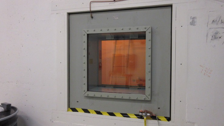
Thursday, February 09, 2017, 14:07, Isaac Earle, North Hot-Cell, Development, , , North Hot Cell Shielding Window Gaskets Changed 23x
|
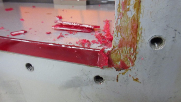
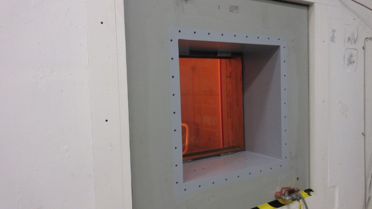
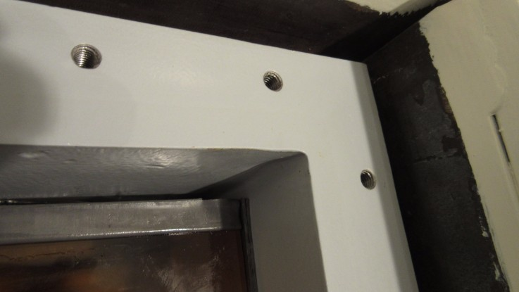
The North Hot Cell shielding window gaskets have been changed and the window has been filled with new oil. Although there was no noticeable oil leaks before starting the job, the gaskets had not been changed since initial installation approximately 15 years ago, so they were done now as part of construction of the new cell. The work took place between January 26 – Feb 8, 2017 following the attached PDF “Full procedure for NHC shielding window gasket change” which references “Gasket change procedure from Hot Cell Services” (also attached).
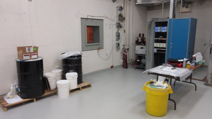
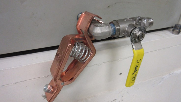
To drain the window a 1/2”polyethylene hose was attached to the drain line using a Swagelok fitting and routed into a 55 gallon drum. A vent valve on the expansion tank was opened to allow air to enter the window. It took approximately 5 hours to drain the window using this method. Approximately 50 US gallons were drained from the window, agreeing with the amount specified on Hot Cell Services drawing #96173-100 (attached).
After draining, the window was purged with helium then pressurized to approximately 13” WC with helium. A pressure drop of 0.6” WC was observed over a 2 hour period. While pressurized, a Varian G8601-60001 leak detector was used to sniff for helium around the perimeter of the gaskets on both the hot and cold sides – no helium leaks detected. A small leak was found on the pressure gauge used to monitor helium pressure.
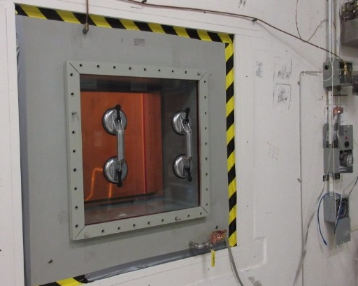
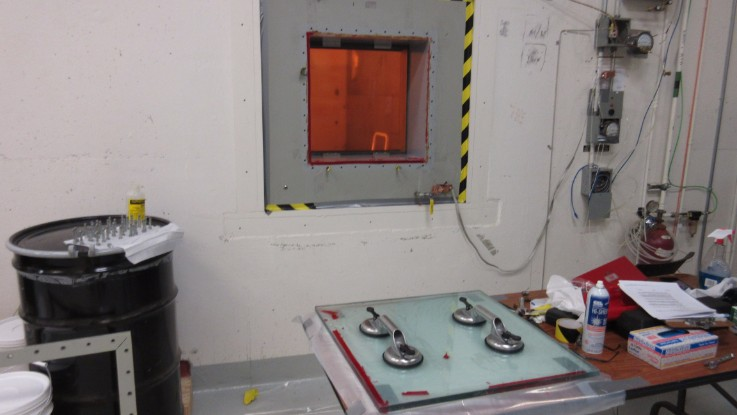
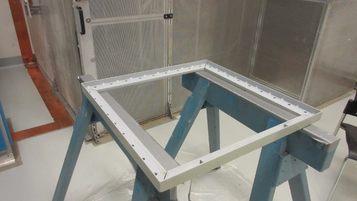
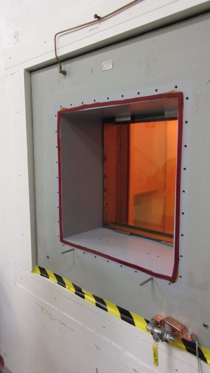
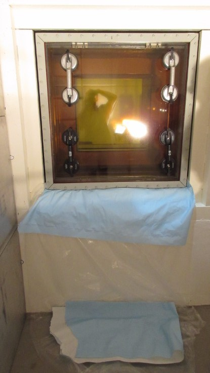
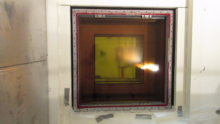
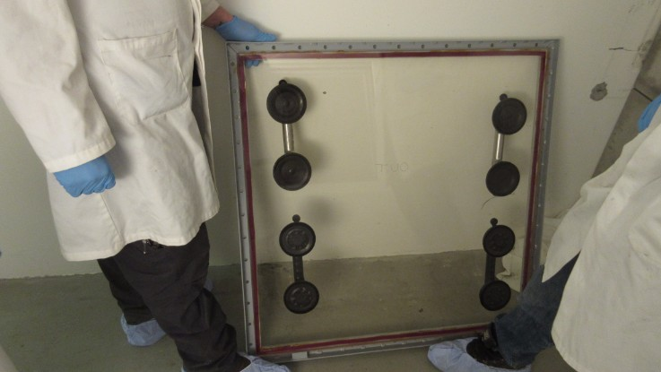
The cold side cover panel assembly was then removed following the HCS procedure. From HCS Drawing #96173-100, the weight of the cold side glass cover panel was estimated to be approximately 50lbs. The guide pins used were McMaster-Carr PN# 93460A385. The trim frame could be easily removed, however the glass panel was stuck to the window housing. A putty knife and isopropyl alcohol were used to cut through the gasket to separate the window from the housing. The alcohol did not damage the paint of the housing – acetone was also tested on a small area and did not cause damage to the paint. Two suction cup handles were used to transport the glass panel, and it was easily lifted by two people. Various methods were attempted to remove old gasket material and gasket adhesive from the trim frame and housing surfaces – the most successful was using a razor blade scraper to remove the majority of the material, followed by an acetone wipe to remove the remainder of the stuck-on gasket adhesive. The panel was reinstalled with new gaskets following the attached procedures - no issues encountered. After torqueing the trim frame bolts the window was leak checked as before. A drop of 0.8” WC was observed over two hours, and no helium could be detected around the perimeter of the new cold side gasket.
The hot side cover panel assembly was changed using the same method as for the cold side. The glass panel was estimated to be 150lbs. A small amount of oil (< 0.5 L) remained behind the hot side glass panel after draining which spilled out after removal of the glass. Four suction cup handles were used, and four people were required to remove and reinstall the panel. After installation the leak check was repeated with a drop of 0.3” WC observed over two hours, and no helium detectable around the perimeter of the hot side gasket.
The replacement gaskets were ordered from Hot Cell Services under PO# 3033973 matching the material and sizes specified on HCS drawing #96173-100.
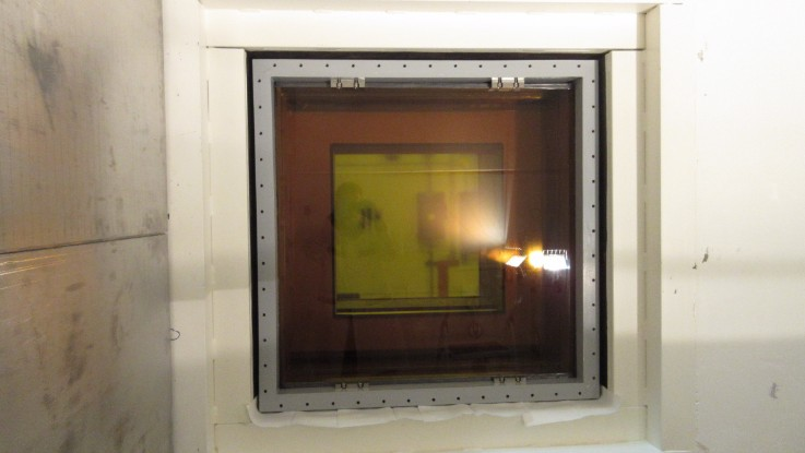
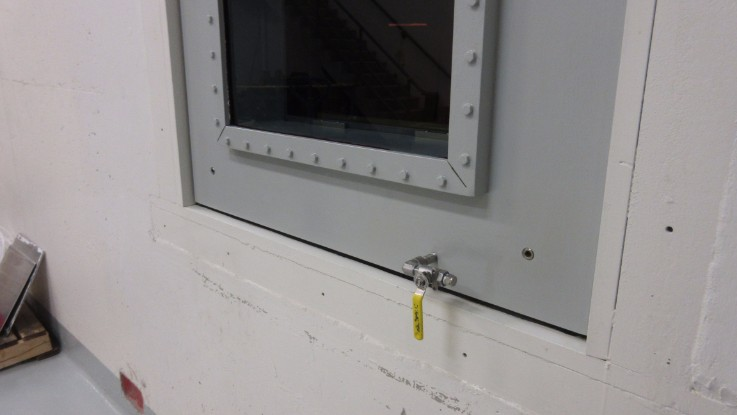
The window was filled with Drakeol 10B LT MIN OIL NF, Product code: PEN1550-00-C-DR, PO #3034657. The window was filled by lifting the drum onto the walkway leading to the target hall entrance, and siphoning the oil out of the drum with a 1/2” polyethylene tube connected to the drain fitting, and an air vent open on the expansion tank. Oil was added until the expansion tank was approximately 80% full.
After filling was complete, the cold side housing was repainted using Macropoxy 646 epoxy paint, 4019 Flint Gray. When the inside of the NHC is next accessible the hot side trim frame bolts will be re-painted to protect the bare metal exposed from removing and reinstalling them.
Note that a quote for $74,313 ($56,823 USD) (PDF attached) was received from Hot Cell Services for them to do this job. We were able to successfully complete this ourselves with approximately $4500 required for the gaskets, $200 for other materials, and roughly 8 FTE days of work.

|
|
Wednesday, May 04, 2016, 11:14, Isaac Earle, North Hot-Cell, Development, , , North Hot Cell Scope Decision
|
A meeting was held on May 4, 2016 to determine the scope of the North Hot Cell project. The following was agreed upon by those in attendance:
The NHC will be a designated target change hot cell. It will be capable of performing all routine target operations (target removal/installation, leak check, electrical check, video inspection, post irradiation examination, target waste packaging and removal) using the same method currently used in the south hot cell. Provisions will be included for the ability to perform target waste separation in the future unless a significant obstacle is encountered in which case the meeting attendees will be consulted. Target waste separation involves separating the internal target heater from the target heat shield, then combining multiple target heaters in a single F-308 shipment. Neither an inert gas atmosphere nor a double-door waste transfer system will be part of the NHC scope.
The following people were in attendance: Bob Laxdal, Anders Mjos, Don Jackson, Joe Mildenberger, Friedhelm Ames, Alex Gottberg, Grant Minor, Yasmine Saboui, Peter Kunz
The following people were invited, but were unable to attend: Chad Fisher, Pierre Bricault
The project will begin immediately, with Isaac Earle as the project leader. The first steps will be to submit a Project Initiation Sheet, then to write and release the Requirements Specification document. |
|
Friday, July 29, 2016, 14:27, Isaac Earle, North Hot-Cell, Development, , , North Hot Cell Measurements & Cleanup
|
The North Hot Cell was accessed today via the Ante Room for inspection, measurements, and clean-up. There were no modules in the SHC or TCS, and no spent targets in the SHC. Under these conditions the maximum field in the NHC was approximately 2μSv/hr. The inside of the cell was cleaned and swept, followed by a floor swipe to check for contamination (none found). All areas of the ante room floor were also swiped: no contamination found.
The following measurements were taken in the NHC for comparison with the Soldiworks model:
SHC/NHC feedthrough panel fastener size: 1/4"-20, 1/2" long
NHC west wall to east edge of SEG block: 33-1/4" on south side, 33" on north side
NHC west wall to furthest extent of TCS (IRH1170): 40"
NHC west wall to wall indentation for viewing window: 46-7/8"
NHC west wall to end of existing ventilation duct: 4-1/8"
|
|
Wednesday, June 30, 2021, 14:11, Matthew Gareau, North Hot-Cell, Standard Operation, , , North Hot Cell Commemorative Opening
|
Yesterday a bottle of Cava (sparkling wine) was place, opened, and poured in the NHC, to commemorate its new operational status.
The NHC is now a functional hot cell and is ready for many years of target exchanges to come. |
|